
Fluorescent sensor on basis of multichannel structures

a fluorescent sensor and multi-channel technology, applied in the field of chemical and biological analysis, can solve the problems of increasing analysis time, and achieve the effects of improving analytical methods kinetic characteristics, reducing the cost of fluorescent sensor manufacturing, and widening the range of solutions analyzed

Inactive Publication Date: 2007-09-18
INST FOR ROENTGEN OPTICS
View PDF14 Cites 9 Cited by
  • Summary
  • Abstract
  • Description
  • Claims
  • Application Information

AI Technical Summary

Benefits of technology

"The invention proposes a fluorescent sensor that is easier and less expensive to manufacture, can analyze a wider range of solutions, and has improved kinetic characteristics. The sensor has a multichannel structure with microchannels filled with sorbent microgranules. The thickness of the aqueous layer in the microchannels is controlled to improve the isolation of the sorbent granules and reduce analysis time. The sensor can be used in various analytical devices and can be designed in a compact way for hard-to-reach points of analysis. The use of polycapillary tube with microchannels and organic substance layers allows for the separation of components with different fluorescent signals and improves the analysis sensitivity. The multichannel structure can be made in the form of a straight or curved length of polycapillary tube, and it can be utilized in analytical units placed in the stream of the solution being analyzed. The organic substance can be in solid or liquid phase."

Problems solved by technology

The reason of this is lies in the fact that further increase in thickness of said layer brings about no improvements in partitioning of said layer and organic substance layer, that is, makes no further contribution to better isolation of sorbent granule from the organic substance, but results instead in the increase of analysis time due to a growth in diffusion time of components being sorbed in aqueous or aqueous solution layer.

Method used


Image

  • Fluorescent sensor on basis of multichannel structures
  • Fluorescent sensor on basis of multichannel structures
  • Fluorescent sensor on basis of multichannel structures

Examples


Embodiment Construction

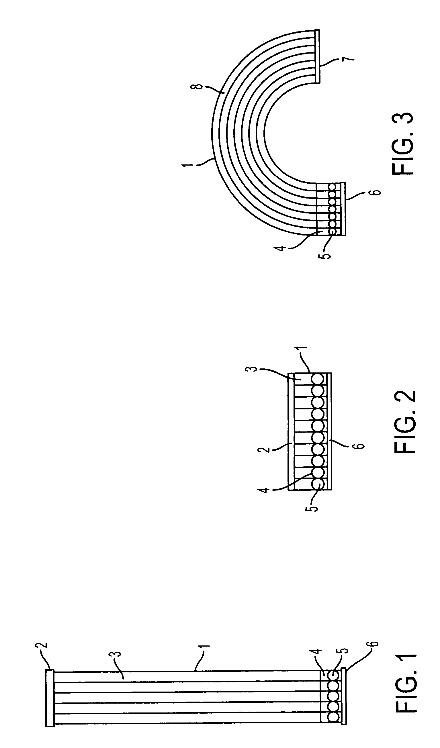
[0064]Fluorescent sensor on basis of multichannel structures according to the invention proposed is constructed as follows. A length 1 of polycapillary tube (FIG. 1), for example, made of glass or quartz, with hundreds of thousand of through capillaries (microchannels) of the same size from units to hundreds micron in transverse section, is hermetically sealed on the side of upper end face with a layer 2 of inert material. Within each microchannel two substance layers are situated. The upper layer 3 is formed of organic substance, and the lower layer 4 is formed of water or aqueous solution. In this layer, sorbent microgranule 5 is located under conditions of free movement, having maximum diameter smaller (for example, by 10-20%) than the internal diameter of microchannel. Lower end face is covered with a layer 6 of inert filtering material having diameter of pores smaller than the diameter of sorbent microgranules.

[0065]Multichannel polycapillary structure forming a part of the sen...


PUM

PropertyMeasurementUnit
Thicknessaaaaaaaaaa
thicknessaaaaaaaaaa
grain sizeaaaaaaaaaa

Abstract

Sensor for use in highly sensitive analytical devices for qualitative and quantitative analysis of natural waters and technology-related solutions, containing low concentrations of components determined. Design of a sensor provides for simplification and costs reduction of its manufacture, widening range of solutions analyzed, improvement of their kinetic characteristics and increase in analysis sensitivity. Sensor has multichannel structure in a form of a piece 1 of a polycapillary tube with through capillaries forming microchannels filled up with two layers of immiscible substances. One layer (4) is formed of water or aqueous solution, and another layer (3) is formed of organic substance. The first of the layers in microchannels contains sorbent microgranules 5.

Description

FIELD OF THE INVENTION[0001]The invention relates to the field of chemical and biological analysis and may be used for development of highly sensitive analytical devices for qualitative and quantitative analysis of aqueous and organic solutions, namely, natural waters and technology-related solutions containing low concentrations of inorganic and organic components being determined, as well as solutions containing biologically active compounds.BACKGROUND ART[0002]Chemical and biological sensors [1-5] are sensing elements providing direct information on ion or molecular composition of the medium (solution) the sensor is immersed in, without its sampling and preconditioning for analysis. Sensors are used in combination with any analytical registering device. To be used for determination of microcomponents in solutions, the sensors should possess ability for selective adsorption (sorption) of components being determined from these solutions, as well as ability to accumulate these compo...

Claims


Application Information

Patent Timeline
Patent Type & Authority Patents(United States)
IPC IPC(8): G01N21/01G01N1/10G01N21/03G01N23/223G01N21/25G01N21/64
CPCG01N21/6452G01N21/645G01N2035/1039
Inventor KHAMIZOV, RUSLAN KH.KUMAKHOV, MURADIN A.NIKITINA, SVETLANA V.MIKHIN, VICTOR A.ZHIGULEVA, TATIANA I.AVOTYNSH, NIKOLAI O.
Owner INST FOR ROENTGEN OPTICS
Learn More