
Combined temperature and color-temperature control and compensation method for microdisplay systems

a microdisplay system and temperature control technology, applied in static indicating devices, cathode-ray tube indicators, instruments, etc., can solve the problems of limited usefulness of particular approaches, difficult color balancing, and compound color balancing difficulties, so as to keep the appearance of the display stable

Active Publication Date: 2007-09-18
GOOGLE LLC
View PDF8 Cites 29 Cited by
  • Summary
  • Abstract
  • Description
  • Claims
  • Application Information

AI Technical Summary

Benefits of technology

[0020]It is therefore an object of the present invention to provide new and improved means to adjust the white point of a liquid crystal on silicon display while that display operates in a temperature regime outside the nominal design point or while that display encounters a temperature change normally experienced at power on, or similar circumstances. The purpose of the invention is to keep the appearance of the display stable over a range of environmental conditions.

Problems solved by technology

Since microdislay systems, especially the liquid crystal on silicon (LCOS) Microdisplay frequently operate in the hot interior of a projection device, the microdisplay technology is still challenged by the need to effectively control the temperature and compensate for the color balancing under the circumstances of temperature increase such that the quality of display would not be impaired by uncontrolled high temperatures.
The difficulties of color balancing are compounded because the display from each color element has its own individual temperature variations and each color element also has different temperature sensitivities.
In the application of such techniques to projection systems based on microdisplays and spatial light modulator, some problems arise.
First, the microdisplays most often operate in the hot interior of a projection device.
A technical challenge is faced by the microdisplay system to provide a method of determining the temperature of the liquid crystal to develop and implement control methods that mitigate the effects of high or low temperature through temperature control or other compensation and that simultaneously maintain proper color balance.
However, the availability of the materials employed and special manufacture processes and mode of operations would significantly restrict the usefulness of the proposed microdisplay systems.
However, this particular approach is of limited usefulness because the method requires a very specific approach to the design and manufacture of the cell.
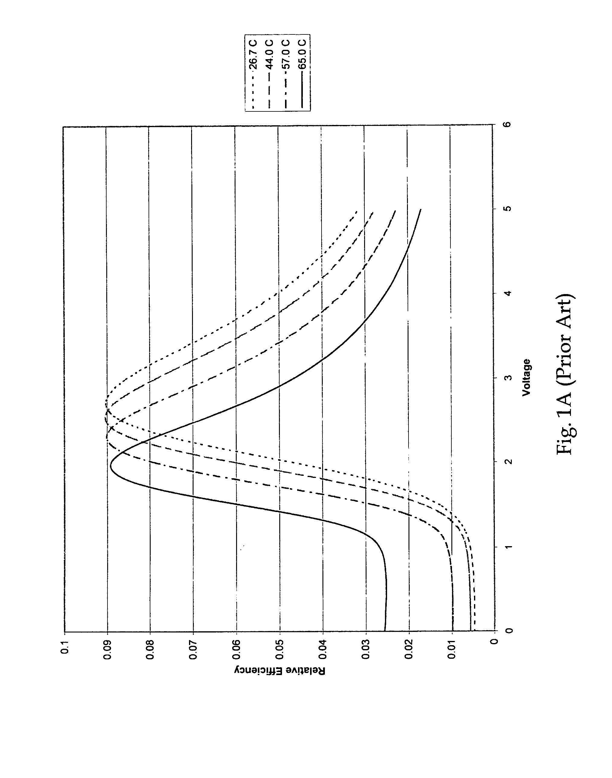
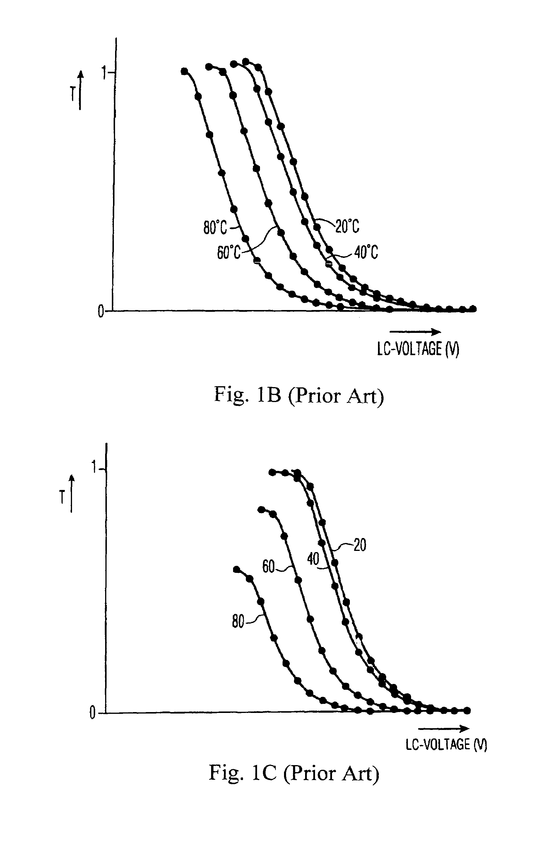
One particular aspect of this temperature driven effect is that the dark state rises as temperature deviates from the design temperature and therefore the contrast of such a system suffers.
Second, the intensity of the achievable dark state rises as temperature rises.
Third, the location of the peak of the voltage curves shifts to lower voltages as the temperature rises.
Fourth, the height of the peak of the voltage curve drops slightly as temperature rises.
The control and compensation of temperature variation for microdisplay system according to the disclosed techniques would become more cumbersome and inconvenient due to this adjustment requirement.
However, as of now, the conventional technologies in microdisplay temperature control still have not fully take advantage of the availability of different control mechanisms to improve and enhance the temperature control and compensation for microdisplay systems operated under widely varying temperatures.
Furthermore, since the microdisplays are sensitive to variations from the design temperature.
However, there are always circumstances where the ambient cannot match the exact circumstances predicted.

Method used


Image

  • Combined temperature and color-temperature control and compensation method for microdisplay systems
  • Combined temperature and color-temperature control and compensation method for microdisplay systems
  • Combined temperature and color-temperature control and compensation method for microdisplay systems

Examples


Embodiment Construction

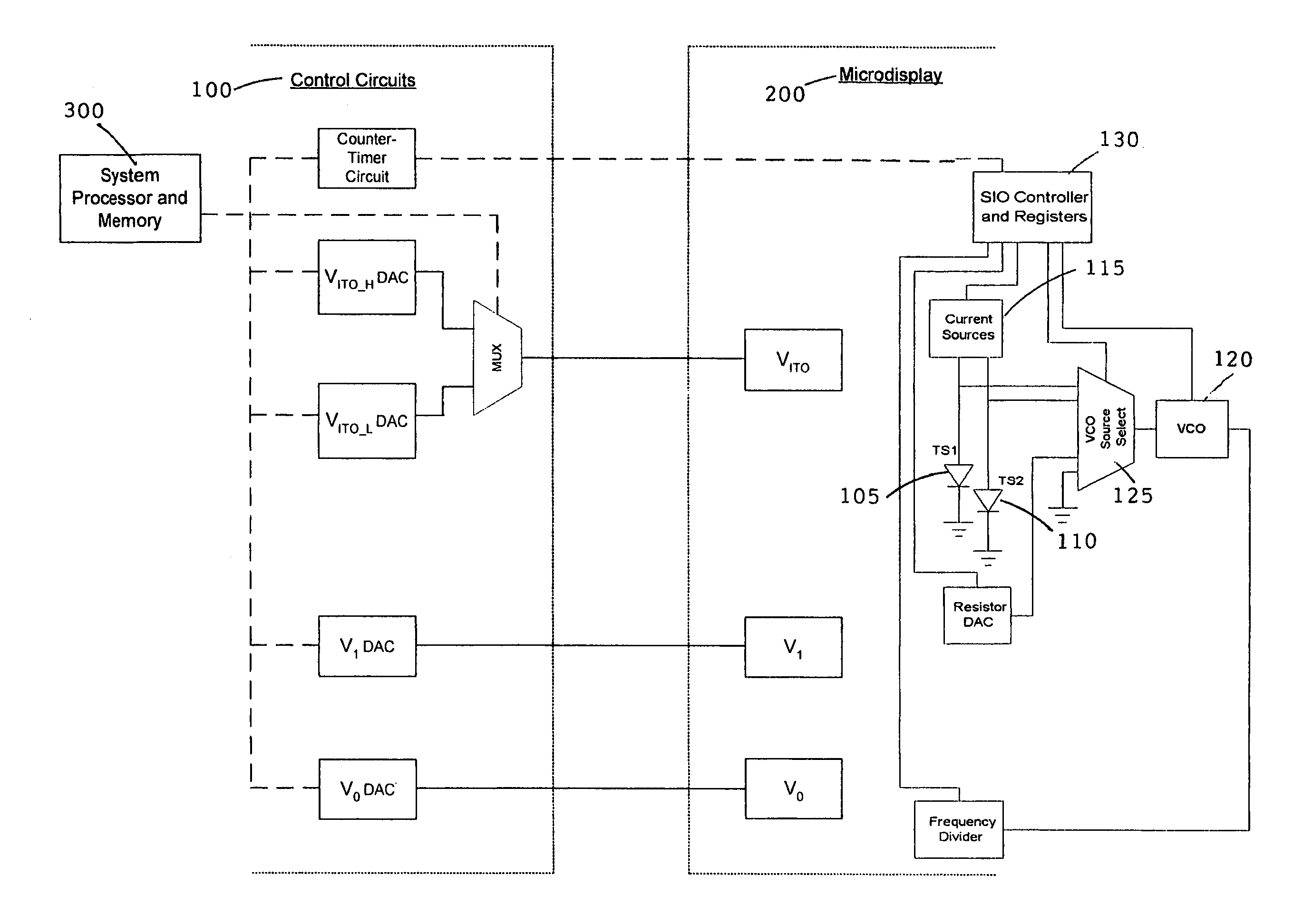
[0034]Referring to FIG. 2 for the basic interfaces between the microdisplay controller 100 and the microdisplay device 200. The signals of temperature measurements are provided to the controller 100 from the temperature sensor shown as TS1105 and TS2110. In another co-pending patent application Ser. No. 10 / 627,230 submitted by a co-inventor of this Application, the details of the temperature measurement system are described. The patent application Ser. No. 10 / 627,230 is hereby incorporated as reference in this Application. In a preferred embodiment of the temperature sensing system as disclosed in the co-pending Application includes two diodes of two unequal current drains as shown as TS1 and TS2. The currents passed from the current source 115 through the two temperature sensing diodes TS1105 and TS2110 are applied to a voltage controlled oscillator VCO 120 via a VCO source selecting device 125 to generate an output signal as frequency that dependent on the temperature measurements...


PUM


Abstract

A temperature control and compensation system is implemented by employing a closely coupled electrical architecture that applies the measured microdisplay temperature, one for each color channel, together with lookup tables preloaded with measured or predicted data for a display, to modify the liquid crystal voltage operating range of each microdisplay as required to achieve and maintain the proper white point operating point for the display. The electrical architecture includes functional blocks as required for realizing the temperature compensation and control for each color channel. The system microprocessor and control unit employs a lookup table to set the control registers on each microdisplay controller with values according to a computed value using the data retrieved from the lookup tables. The range of values in the lookup table includes setups for a number of varied conditions. One of these conditions is temperature.

Description

[0001]This Application is a Continuation-in-Part (CIP) Application and claim a Priority Date of Oct. 11, 2002 benefited from a Provisional Patent Application 60 / 417,786 file by one common inventor of this patent application.BACKGROUND OF THE INVENTION[0002]1. Field of the Invention[0003]The present invention pertains to liquid crystal on silicon (LCOS) displays, and more particularly to improved temperature and color temperature control and compensation method for the microdisplay systems.[0004]2. Description of the Prior Art[0005]Since microdislay systems, especially the liquid crystal on silicon (LCOS) Microdisplay frequently operate in the hot interior of a projection device, the microdisplay technology is still challenged by the need to effectively control the temperature and compensate for the color balancing under the circumstances of temperature increase such that the quality of display would not be impaired by uncontrolled high temperatures. The difficulties of color balanci...

Claims


Application Information

Patent Timeline
IPC IPC(8): G09G3/36G09G5/02
CPCG09G3/3696G09G5/02G09G2320/041
Inventor HUDSON, EDWIN LYLEMCDONALD, DAVID CHARLES
Owner GOOGLE LLC
Learn More