
2D/3D data projector

a data projector and projector technology, applied in projectors, color televisions, television systems, etc., can solve the problems of large inability to display large visual images with very small devices, inability to achieve large-scale image display, etc., to achieve small power consumption, reduce the effect of photon loss, and reduce the size of current data projectors

Inactive Publication Date: 2007-09-18
UPSTREAM ENG
View PDF37 Cites 26 Cited by
  • Summary
  • Abstract
  • Description
  • Claims
  • Application Information

AI Technical Summary

Benefits of technology

"The invention is a small and affordable data projector that can show both 2D and 3D images. It uses a micro display and a special light source chip with a diffractive element to create a uniform and bright image. The projector has a high power efficiency and is easy to switch between 2D and 3D modes. Overall, the invention provides a compact and versatile tool for projecting images in a unique way."

Problems solved by technology

As the size becomes smaller and the functionality higher, there is a fundamental problem of showing large enough visual images with very small devices.
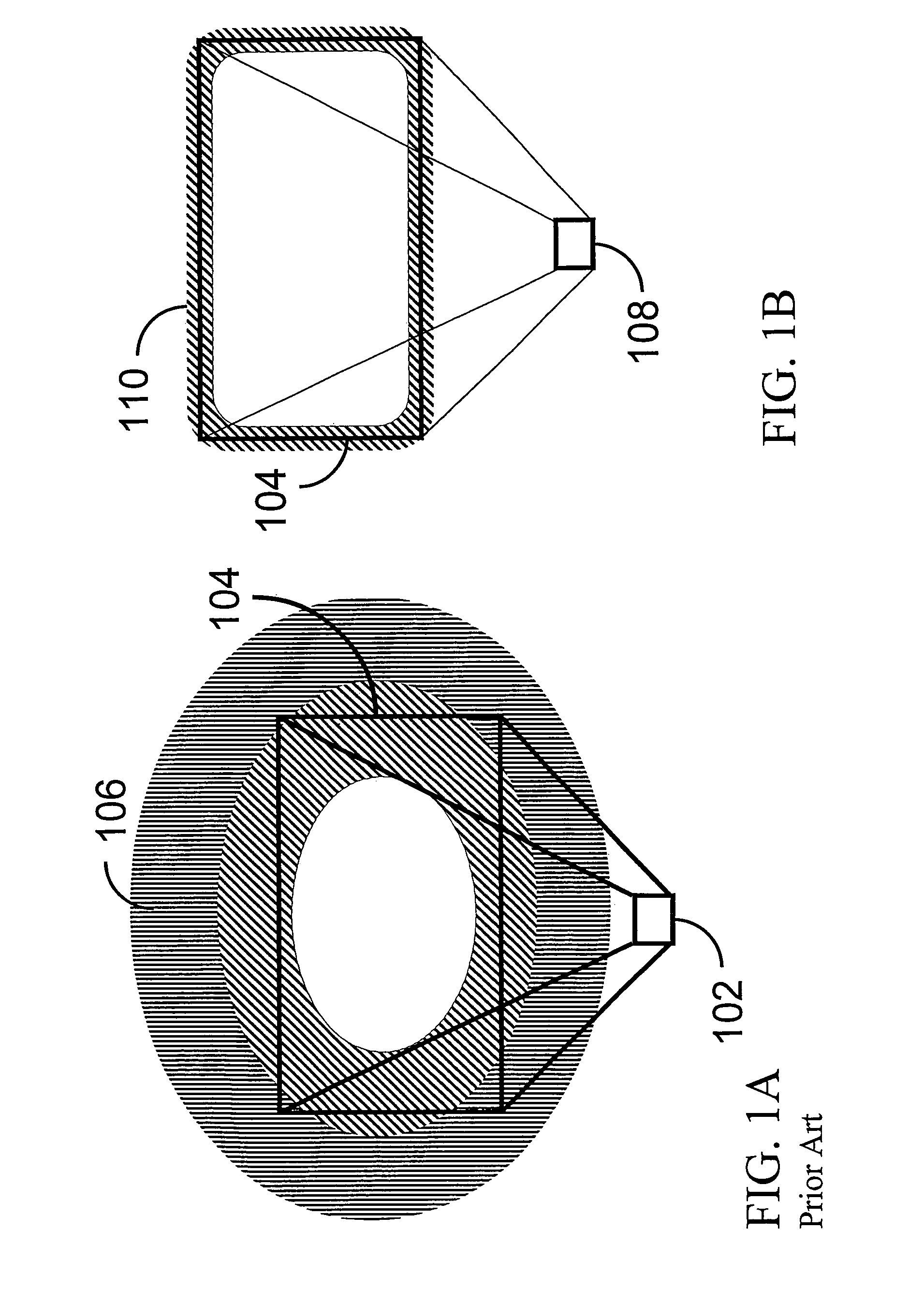
However, the current data projectors are large in size and inefficient in nature.
These light sources have inherently low efficiency and produce heat, which consumes high amounts of energy and requires a cooling system.
However, these solutions do not have well enough optical efficiency.
In these systems, the light source has poor external efficiency, and in addition to that, a large part of the light is lost in collimation.
Secondly, these solutions are still large in size and expensive with high power consumption, and they cannot be operated with widely used battery technologies.
Another issue that is of interest to large audiences in image projection is the issue of 3-dimensional (3D) projection.
The current data projectors are not inherently capable of showing full color 3D images and the special devices that are designed to do so are expensive and rare.

Method used


Image

  • 2D/3D data projector
  • 2D/3D data projector
  • 2D/3D data projector

Examples


Embodiment Construction

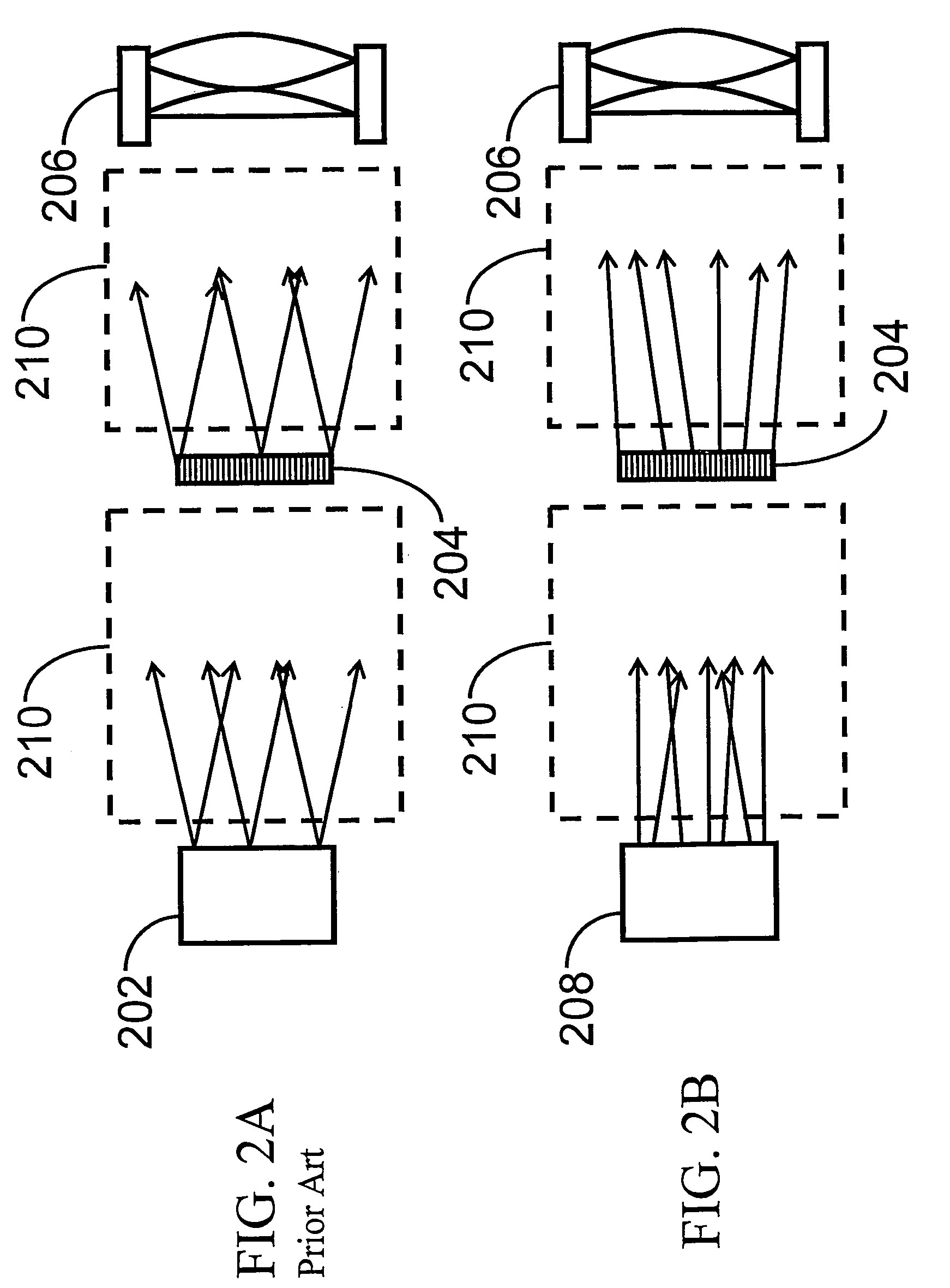
[0041]The efficiency of the projector is degraded by the losses which include: spectral losses (if wideband sources are used), losses due to poor internal efficiency of the source, losses due to poor external efficiency of the source (for example with LEDs), light collection losses (collimation losses), integration losses (if several light beams are combined), color separation losses (losses in dichroic mirrors used to split the light into red, green and blue components), polarization losses (if LC-micro display is used), reflection or transmission losses at the micro display itself for example due to a poor fill factor (gaps between the pixels), color combination losses (for example when using X-cube or dichroic mirrors), and losses in the projection lens (reflection losses on the lens surfaces).

[0042]It is extremely important that the light loss is minimized in every aspect. It is also desirable to be able to maximize the internal and external quantum efficiencies of the light sou...


PUM


Abstract

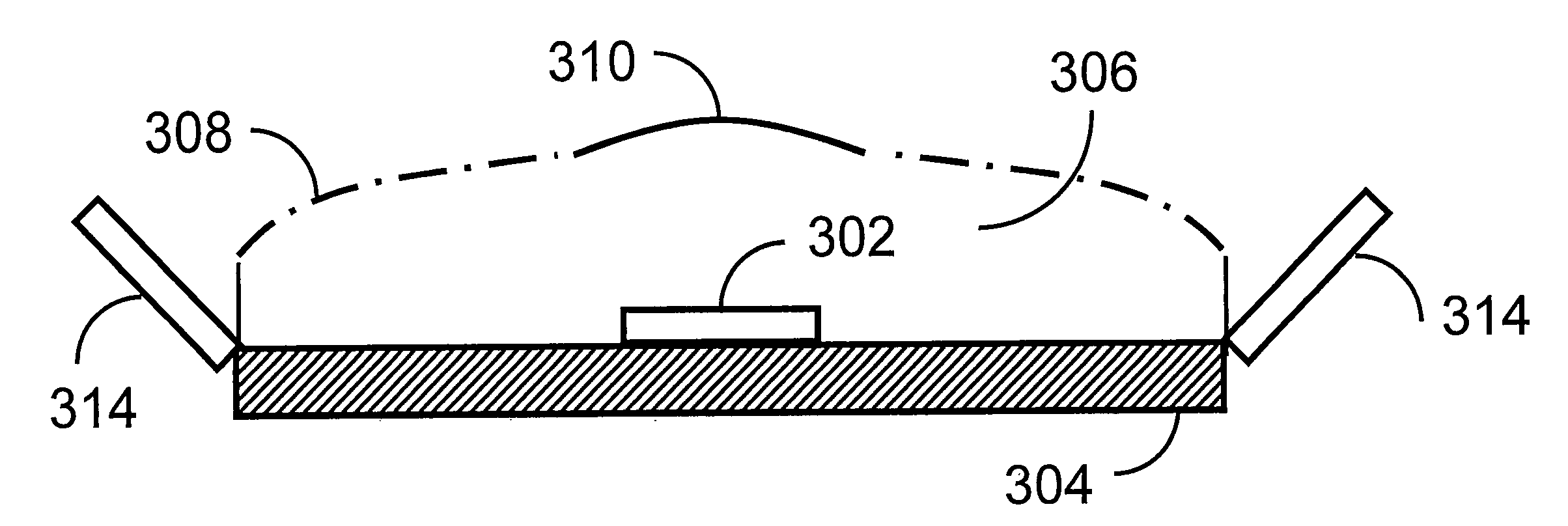
The present solution relates to a 2D / 3D data projector, which comprises: A data projector, the data projector comprising: at least one micro display having an image to be projected, at least one source unit comprising at least one light source chip and at least one beam forming component, each beam forming component comprising at least one diffractive element, and each source unit being designed to preserve etendue as far as possible, to minimize photon loss, to provide a desired projection shape and a uniform illumination onto the micro display, and a focusing optical unit for projecting the image of the micro display on a target.

Description

CROSS-REFERENCE TO RELATED APPLICATION[0001]This application is a continuation of now-allowed U.S. patent application Ser. No. 10 / 622,296, entitled identical to this application and which was filed on Jul. 17, 2003 now U.S. Pat. No. 7,059,728 and which further claimed priority to Finland Pat. Application No. 20030583 filed on Apr. 16, 2003. This application claims priority to the two applications above, each of which is hereby incorporated by reference.TECHNICAL FIELD[0002]The invention relates to devices for displaying images by projection.BACKGROUND[0003]The current trend of mobility drives the consumer demand towards ever smaller portable devices, such as mobile phones, portable digital assistants, music and video players, laptop PCs, head mounted displays etc. As the size becomes smaller and the functionality higher, there is a fundamental problem of showing large enough visual images with very small devices. Because the size of a fixed screen cannot grow without increasing the ...

Claims


Application Information

Patent Timeline
Patent Type & Authority Patents(United States)
IPC IPC(8): F21V7/22F21Y101/00G02B5/04G02B27/09G02B27/28G02B30/25H01L25/00H01L27/15H01L33/60H01S5/40H04N5/74H04N9/31
CPCG02B27/102G02B27/1066G02B27/145H04N9/315G02B27/285G02B27/149H01L33/60G03B21/00H04N5/74
Inventor ALASAARELA, MIKKO PETTERIALASAARELA, ILKKA ANTERO
Owner UPSTREAM ENG
Learn More