
Plug-and-socket connector

a plug-and-socket connector, multi-row technology, applied in the direction of coupling device connection, coupling protective earth/shielding arrangement, electrical apparatus, etc., can solve the problems of mechanical attachment of printed circuit board, ineffective shielding of individual electrically conductive contact elements, and special ineffective shielding types, etc., to achieve great mechanical stability and low production costs

Active Publication Date: 2007-09-11
ERNI PRODION GMBH
View PDF21 Cites 121 Cited by
  • Summary
  • Abstract
  • Description
  • Claims
  • Application Information

AI Technical Summary

Benefits of technology

The solution provides high-quality integration of THR technology with SMT, enabling high-frequency data transmission rates up to 10 Gbit / s and increased mechanical stability with pull-out forces four to eight times greater than comparable components, while maintaining low production costs and miniaturization.

Problems solved by technology

A disadvantage of this plug-and-socket connector is that the mechanical attachment of the printed circuit board takes place by means of a screw connection, whereby the outer shielding elements are fixed in place at the same time.
This type of shielding is not effective for shielding individual electrically conductive contact elements or groups of contact elements, which are particularly multi-pole and furthermore disposed in multiple rows in plug-and-socket connectors provided for the applications mentioned initially.
This type of shielding is particularly ineffective if high data rates or high-frequency signals are being transmitted.

Method used


Image

  • Plug-and-socket connector
  • Plug-and-socket connector
  • Plug-and-socket connector

Examples


Embodiment Construction

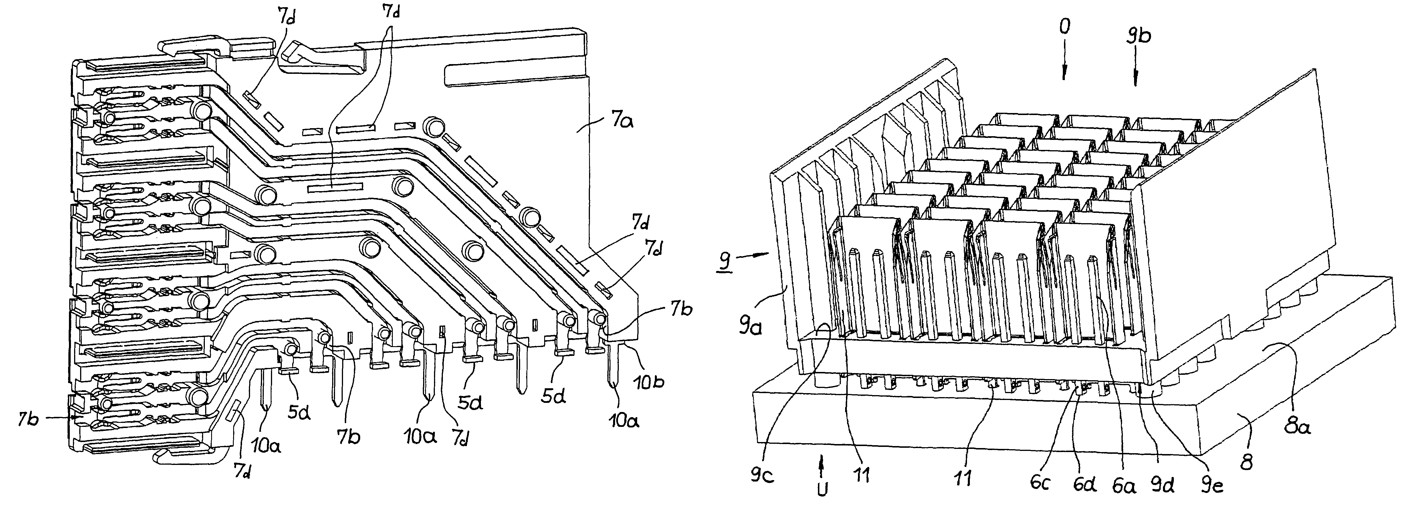
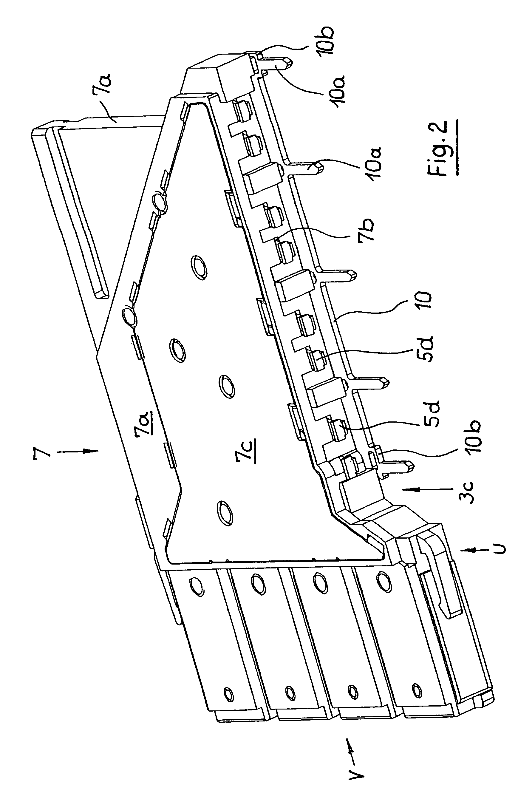
[0033]Referring to FIGS. 1-7, the first exemplary embodiment of the plug-and-socket connector configured according to the invention, shown in various views and detail representations, is a female multi-point connector 1 constructed in modular manner. This female multi-point connector 1 is shown in a perspective view, with the viewing direction from the right rear. To facilitate orientation for the following description, a three-axis direction cross RK with regard to the possible viewing directions looking at the body surfaces of the plug-and-socket connector is drawn onto this female multi-point connector in FIG. 1. The reference symbols disposed on this direction cross “RK” have the following meaning:

[0034]“V”—viewing direction from the front,

[0035]“H”—viewing direction from the rear,

[0036]“L”—viewing direction from the left,

[0037]“R”—viewing direction from the right,

[0038]“O”—viewing direction from the top or above, and

[0039]“U”—viewing direction from the bottom or below, onto the...


PUM


Abstract

A multi-pole, multi-row plug-and-socket connector with shielding, for placement on printed circuit boards, circuit cards, and similar electrical components, which can be used in an electrical or electronic system includes electrical contact parts for the transmission of signals, which possess a connection section on one end and an electrically conductive attachment section on the other end, as well as an electrical shielding, which possesses at least one electrically conductive contact section. The free ends of the electrically conductive attachment sections of the electrical contact parts are SMD contacts. The at least one electrically conductive contact section of the shielding is, at the same time, an attachment pin which projects into a passage hole of the printed circuit board when the plug-and-socket connector is disposed on the same, for the purpose of connective soldering using THR technology.

Description

CROSS REFERENCE TO RELATED APPLICATIONS[0001]Applicant claims priority under 35 U.S.C. §119 of German Application No. 20 2005 020 474.9 filed on Dec. 31, 2005.BACKGROUND OF THE INVENTION[0002]1. Field of the Invention[0003]The present invention relates to a multi-pole, multi-row plug-and-socket connector with shielding, with which electrical lines can be connected with one another, preferably in releasable manner. More particularly, the electrical lines are those of electronic components or modules, particularly printed circuit boards, plug-in cards, and similar system components These plug-and-socket connectors can be so-called male multi-point connectors or female multi-point connectors of a plug-and-socket connection.[0004]2. The Prior Art[0005]Users are making ever greater demands on such plug-and-socket connectors with regard to the electrical and mechanical parameters, particularly with regard to high transmission rates as well as great mechanical strength, particularly with r...

Claims


Application Information

Patent Timeline
Patent Type & Authority Patents(United States)
IPC IPC(8): H01R13/648H01R13/658
CPCH01R13/514H01R12/724H01R13/6587
Inventor LAPPOHN, JURGEN
Owner ERNI PRODION GMBH
Learn More