
Exhaust device with or without dilution based on two controllable outputs

a technology of exhaust circuit and output, which is applied in the direction of mechanical equipment, machines/engines, transportation and packaging, etc., can solve the problems of water entering the exhaust circuit, engine stalling, and devices with drawbacks, and achieve the effect of easy installation in the vehicle and simple manufacturing

Inactive Publication Date: 2007-09-11
NEXTER SYST SA
View PDF10 Cites 2 Cited by
  • Summary
  • Abstract
  • Description
  • Claims
  • Application Information

AI Technical Summary

Benefits of technology

[0012]One advantage of the present invention lies in the fact that it is simple to manufacture and may be easily inserted into a vehicle.
[0013]According to one embodiment, the signature reduction exhaust has an obturating system using plates allowing it to be insulated from the exterior, namely during the immersion of the vehicle.

Problems solved by technology

This device has drawbacks, however.
Indeed, when the device operates constantly, the drawbacks generated by the device are also constant: when the tank is immersed in water there is the risk of water entering the exhaust circuit, and thus of the engine stalling, and the substantial increase in temperature of the cooling elements.
If this device is very useful during operations where the vehicle's stealth is all important, it becomes a hindrance, for example, during maintenance operations where the operators risk getting burned or when fording where it is necessary to mount snorkels.

Method used


Image

  • Exhaust device with or without dilution based on two controllable outputs
  • Exhaust device with or without dilution based on two controllable outputs

Examples


Embodiment Construction

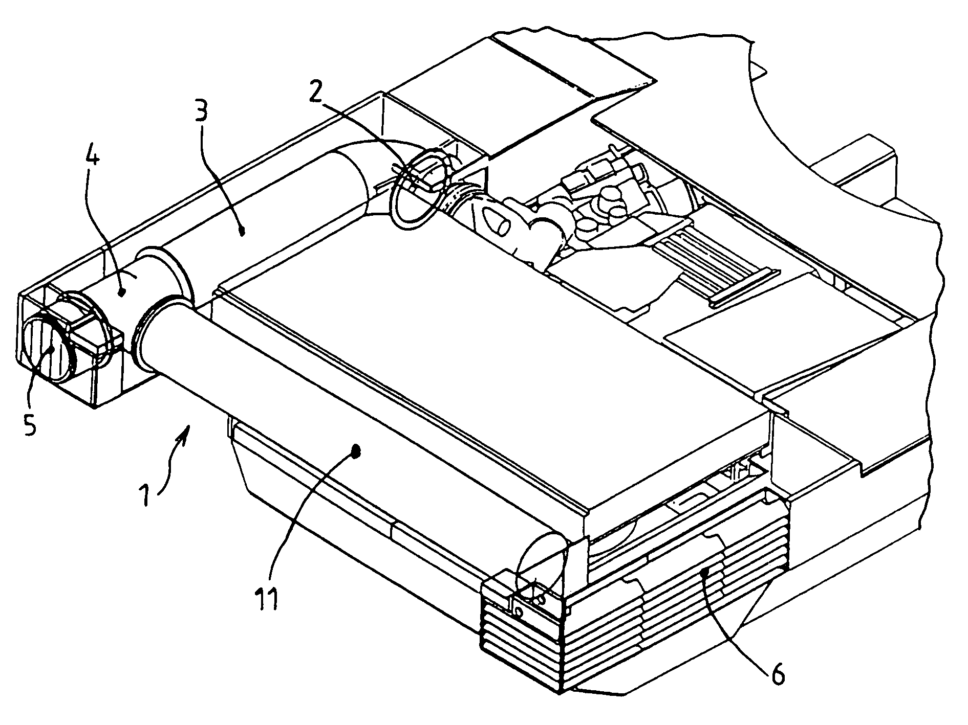
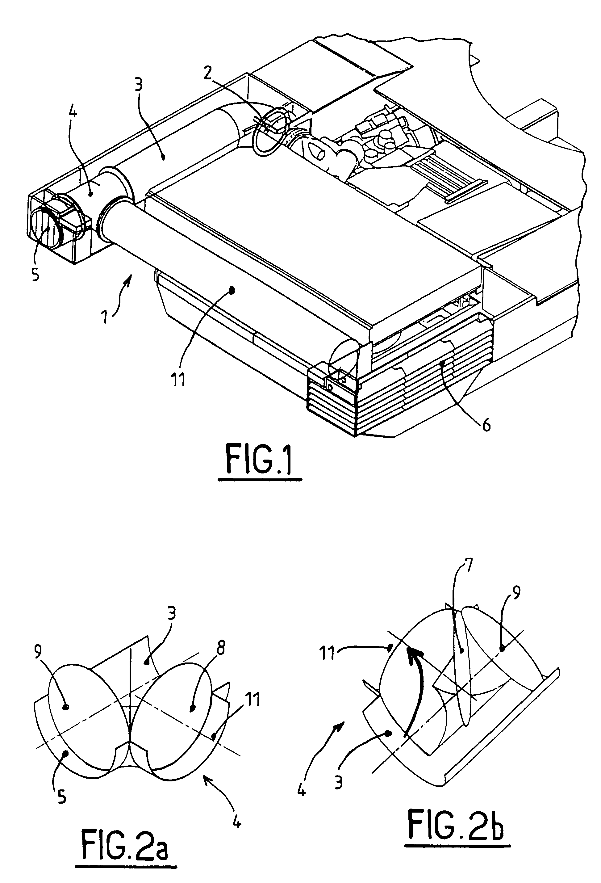
[0017]FIG. 1 shows an exhaust device 1 with two controllable outlets which, according to the invention, is composed of an inlet mouth 2 directly linked to the outlet of the engine's turbocompressor, attached to a pipe 3 opening into a distributor 4 and two exhausts, classical 5 and specific 6. Exhaust 5 is a classical exhaust opening out directly to the exterior. It has no heat dilution device and interfaces such as a snorkel (for example during fording), a deflection elbows or an evacuation sheath (for example to evacuate the gases during workshop maintenance operations) may be adapted onto it. Pipe 11 guides the exhaust gases towards the specific exhaust 6. This exhaust 6 is an exhaust that reduces and dilutes visible, sound and infrared emissions. Such an exhaust is already known and its operating principle does not require further description. However, different types of reduction and dilution exhausts may be envisaged for the visible, sound and infrared emissions. Reference may...


PUM


Abstract

An exhaust gas distribution device for the engine of a vehicle, wherein said device incorporates means to control the evacuation of the gases towards a classical exhaust system or else towards a specific exhaust system, said specific exhaust system incorporating means to dilute and reduce the visible, sound and infrared signatures of said vehicle.

Description

BACKGROUND OF THE INVENTION[0001]1. Field of the Invention[0002]The technical scope of the present invention is that of devices intended to reduce the visible and infrared signatures of vehicles, in particular combat vehicles, with respect to their exhaust gases.[0003]2. Description of the Related Art[0004]Up to now, studies attempting to reduce the infrared signature of armoured vehicles have mainly concentrated on the reduction in radiation of the armoured structure by associating techniques to reduce the temperature of the skin and stealthy materials. It now seems that for a stealthy armoured vehicle, the plume of its exhaust gases is a major element in its detectability. Moreover, the evolution of thermal camera technologies allows hot sources to be detected in the land environment at very large distances. To improve the stealth of these vehicles with respect to the evolution of infrared sensors, it is thus now necessary for the energy level radiated by the exhausts of armoured ...

Claims


Application Information

Patent Timeline
Patent Type & Authority Patents(United States)
IPC IPC(8): F01N7/00F01N13/08F01N13/14
CPCF01N13/08F01N13/087F01N13/14F01N2410/00
Inventor CARLIER, SYLVAINBRUN, MICHELTIMMER, BERNARD
Owner NEXTER SYST SA
Learn More