
Compact actuator with large thrust

a technology of actuators and actuators, applied in mechanical equipment, machines/engines, gearing, etc., can solve the problem of bulky types

Inactive Publication Date: 2007-09-11
KLINGER JOHN HAMILTON
View PDF23 Cites 16 Cited by
  • Summary
  • Abstract
  • Description
  • Claims
  • Application Information

AI Technical Summary

Benefits of technology

"The present invention is a compact actuator that can produce a large output thrust with modest fluid pressure. It can be operated manually or with fluid power, and can combine both in a simple design. The actuator is constructed with a housing, a reaction member, a piston, a rotor, and a plunger, all enclosed within the housing. The actuator is designed to produce output movement only through the application of fluid pressure or through the handle, ensuring that the output is not caused by force from the device being operated."

Problems solved by technology

This type is also bulky.

Method used


Image

  • Compact actuator with large thrust
  • Compact actuator with large thrust
  • Compact actuator with large thrust

Examples


main embodiment

—FIGS. 1A THROUGH 1D—MAIN EMBODIMENT

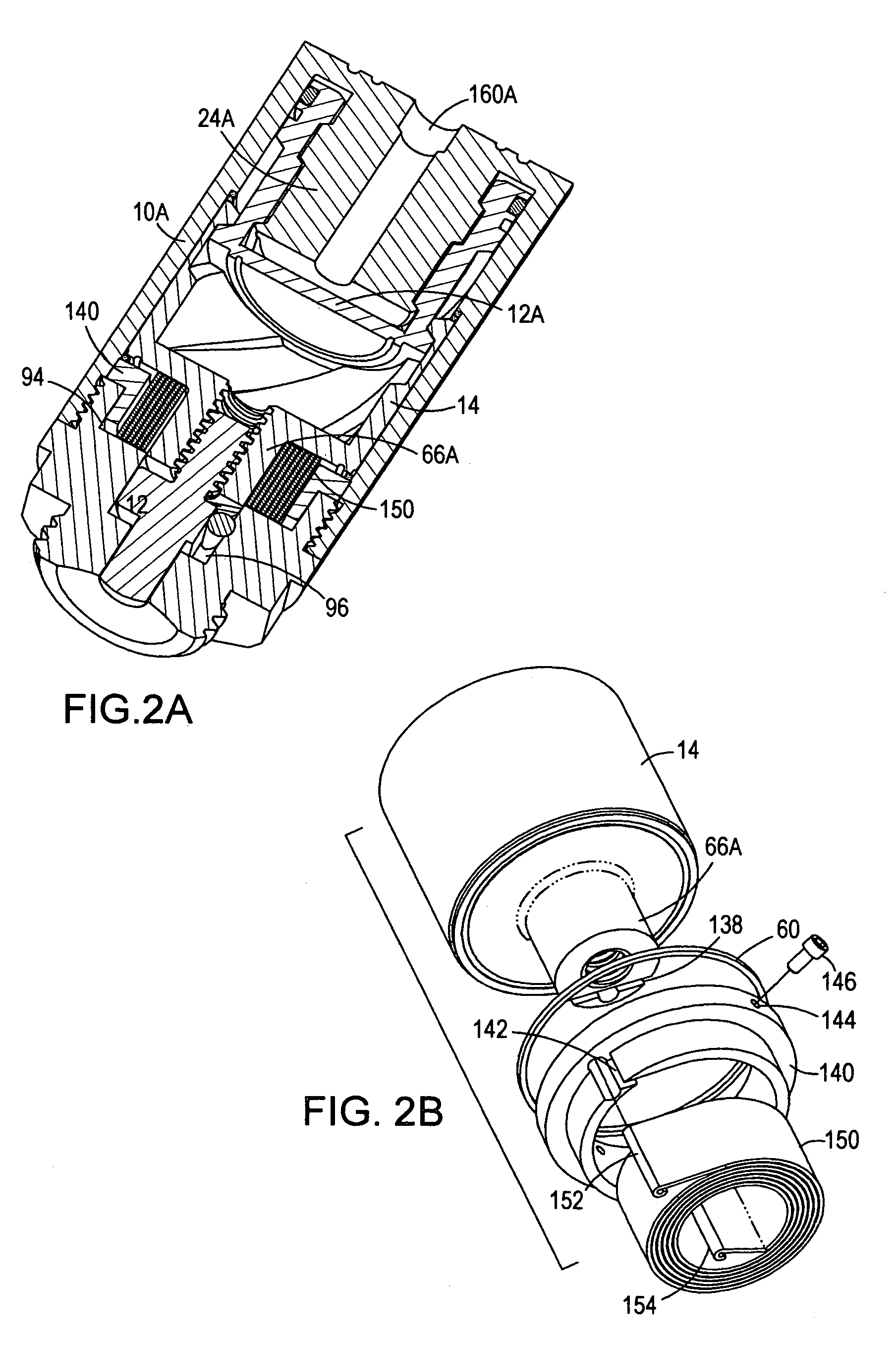
[0036]A main embodiment of the present invention is a double-acting actuator as illustrated in FIGS. 1A (a perspective view), 1B (a perspective partial length-wise sectional view), 1C (a perspective view of the reaction member in isolation) and FIG. 1D (cross-section perpendicular to actuator axis in plane of the anti-rotation Pin 92).

[0037]A cylindrical housing 10 and base 18 enclose all active components of the actuator of this invention, as pictured in FIG. 1A, and its external interfaces consist of a port assembly 22 to which fluid-power is delivered, base mounting threads 90 which attach the actuator to the device it operates, and a plunger extension 76 which transmits force and movement to active element of the device being operated.

[0038]Wholly within the housing 10 are a piston 12 and a rotor 14, together with the various sealing gaskets associated with them and thrust rings 60, while partially within the housing 10 are the port assembly 2...


PUM


Abstract

A manually and / or fluid-pressure operated rotary actuator is coupled with a power screw in a compact assembly to produce large linear thrust. The actuator is operated in both directions by fluid pressure or in one direction by fluid pressure and in the other by spring energy, or by fluid pressure alone or in combination with manually applied force. The actuator has a cylindrical housing, a cylindrical reaction member inside of the housing, a cylindrical piston partially covering the reaction member, a cylindrical rotor partially covering the piston, a device forcing rotation of the piston when moving axially with respect to the reaction member and / or rotor, a plunger engaged with the rotor and restrained from turning with respect to the housing, a base through which the plunger extends, a spring connected to the rotor and housing, a two port assembly, and a handle affixed to the reaction member for manual operation.

Description

CROSS REFERENCE TO RELATED APPLICATIONS[0001]This invention claims the benefit of PPA Ser. No. 60 / 657,682, filed 2005 Mar., 01 by the present inventor.BACKGROUND OF THE INVENTION[0002]1. Field of Invention[0003]This invention relates to a fluid-pressure powered actuator of small diameter producing large thrust, used to operate valves, brakes, and various articulated mechanisms.[0004]2. Prior Art[0005]Actuators powered by pneumatic or hydraulic pressure are the preferred means of remotely operating mechanical devices where the possibility of electrical shock, spark, or electromagnetic interference is too high.[0006]When linear thrust is needed to operate some device, such as the poppet in a valve, actuators are used which vary in construction and complexity, ranging from a single piston in a closed cylinder directly coupled with an output member to more elaborate arrangements of levers and cams coupling a piston or bladder with an output member. Minimizing the cost usually argues for...

Claims


Application Information

Patent Timeline
Patent Type & Authority Patents(United States)
IPC IPC(8): F01B3/08F16H3/06
CPCF15B15/068Y10T74/18592
Inventor KLINGER, JOHN HAMILTON
Owner KLINGER JOHN HAMILTON
Learn More