Magnetic suspension bearing

Inactive Publication Date: 2007-08-28
LI GUOKUN +2
View PDF4 Cites 56 Cited by
  • Summary
  • Abstract
  • Description
  • Claims
  • Application Information

AI Technical Summary

Benefits of technology

[0004]The object of the present invention is to provide an all-permanent magnetic full suspension bearing with a simple structure, low manufacture cost, high stability, great rigidity and great load-bearing capability which can be used widely in various fields.SUMMARY OF THE INVENTION
[0013]In the present invention, due to the fact that one or more permanent magnets are fixed on the shaft directly or indirectly, and matching permanent magnets are provided in certain space, wherein the magnetic polarity and magnitude of magnetic force of said matching magnets match with those of said one or more magnets, such perfect matching in space makes the rotating shaft with permanent magnet fixed thereon to rotate in full suspension with all-permanent magnet by magnetic force without other kinds of support or repulsion, in other words, full magnetic suspension can be achieved with the perfect combination of permanent magnets solely without a complicated electronic control system, auxiliary supporting means, such as that made of superconductor, and other auxiliary means. Accordingly, the present invention has many advantages such as a simple structure, low manufacture cost, high stability, great rigidity and great load-bearing capacity, and can be used widely in various fields.
[0014]According to the present invention, in each one of the radial stable magnetic ring sets, the magnetic poles corresponding to said radial static magnetic ring and said radial movable magnetic ring along the radial direction have the same magnitude of magnetic force with opposite polarities. Similarly, in each one of the axial stable magnetic ring sets, the magnetic poles corresponding to said axial static magnetic ring and said axial movable magnetic ring along the axial direction have the same magnitude of magnetic force with opposite polarities. In this way, pushing and pulling magnetic circuits, i.e. attracting and repelling magnetic circuits, are formed in both the radial direction and the axial direction respectively. Namely, each set of the radial stable magnetic rings and the axial stable magnetic rings are at the lowest energy state when the magnetic poles are in coupling state, and a restoring force will be produced when they are departure from the coupling state. In regard to the axial stable magnetic ring, an axial stablizing force is formed in axial direction so that the shaft will not move in axial direction, but the axial stable magnetic ring could not maintain the shaft stable in radial direction. In regard to the radial stable magnetic ring, because the gravity of the shaft will make the radial movable magnetic ring have a tendency to move downward, the radial static magnetic ring will pull the radial movable magnetic ring upward by a coupling force, and therefore an upward supporting force is formed. Thus, the radial stable magnetic ring makes the shaft stable in radial indirection. However, the radial stable magnetic ring could not make the shaft stable in axial direction. When the alternative axial stable magnetic ring and radial stable magnetic ring cooperate with each other, the shaft can be suspended entirely and meet the requirements of the stability and rigidity by taking into account of other factors, such as gravity. With directly employing the magnetic suspension structure of the present invention, a magnetic suspension bearing with the advantages of simple structure, low manufacture cost, good stability and great rigidity can be manufactured. Since the rigidity is increased with the increase of the number of the magnetic poles, and the number of the poles can be determined according to the requirement of the rigidity, therefore, a magnetic suspension with great rigidity can be manufactured and the present invention can be applied to various fields.

Problems solved by technology

However, the structure of the bearing is very complicated, and it needs an electronic measurement and control system, auxiliary supporting means and other auxiliary means, and accordingly, the manufacture cost is very high, especially for a bearing with a great load-bearing capability.
The conventional permanent magnetic suspension bearing is simple in structure and low in manufacture cost, but limited in load-bearing capability and thereby mainly used in instruments such as electromagnetism meters with monopole or two-pole magnetic suspension and thereby a limited rigidity, namely a small dF / dz (the change rate of the load-bearing force when a gap changes), and therefore is not fit for various applications.

Method used


Image

  • Magnetic suspension bearing
  • Magnetic suspension bearing
  • Magnetic suspension bearing

Examples


first embodiment

THE FIRST EMBODIMENT

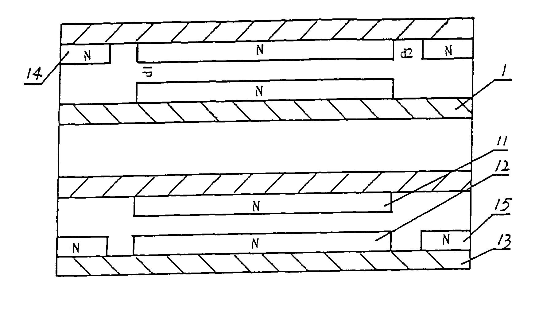
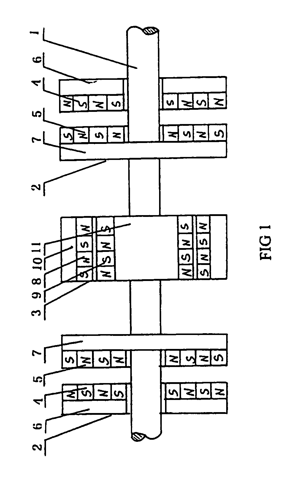
[0023]As shown in FIG. 1, two sets of radial stable magnetic rings 2 are provided on a supported shaft 1. One set of axial stable magnetic rings 3 is provided between the two sets of radial stable magnetic rings 2. The radial stable magnetic rings 2 comprise a radial static magnetic ring 4 and a radial movable magnetic ring 5, which are parallel to each other. The radial static magnetic ring 4 is fixed on a bearing housing 6. The radial movable magnetic ring 5 is fixed on a shaft sleeve 7 which extends in radial direction. The shaft sleeve 7 is integrated with the shaft 1. Four closely connected cross magnetic poles are alternatively provided in the radial static magnetic ring 4, which are S pole, N pole, S pole and N pole from the shaft along the radial direction respectively. Four closely connected cross magnetic poles are alternatively provided in the radial movable magnetic ring 5, which are N pole, S pole, N pole and S pole from the shaft along the radial di...

second embodiment

THE SECOND EMBODIMENT

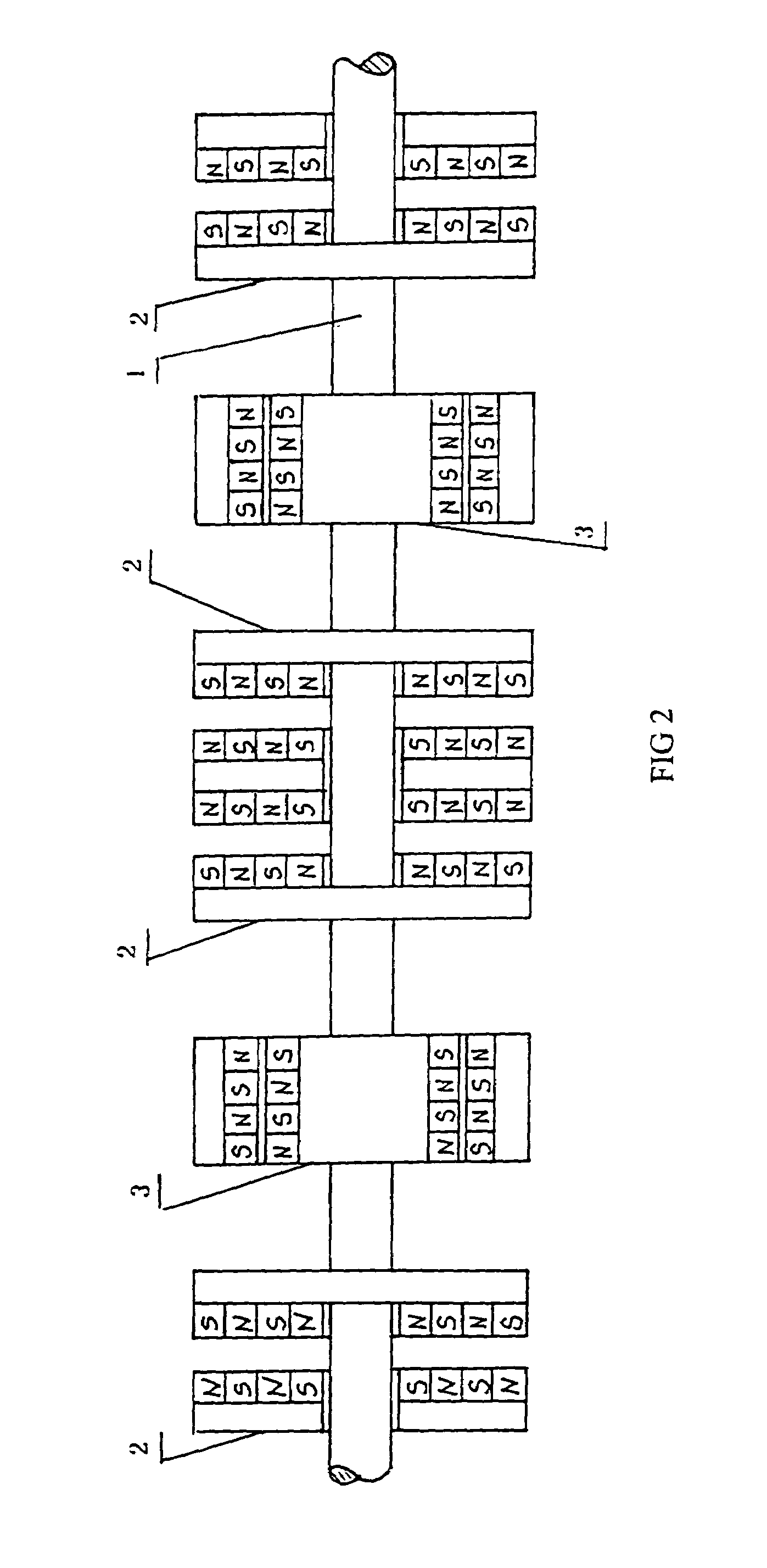
[0029]In this embodiment, four sets of radial stable magnetic rings 2 and two sets of axial stable magnetic rings 3 are provided with an arrangement as shown in FIG. 2. The two sets of axial stable magnetic rings 3 are provided between the two sets of the radial stable magnetic rings 2, respectively. The radial static magnetic rings 4 of the two central sets of the radial stable magnetic rings 2 are fixed on the two sides of the same bearing housing along radial direction. There are also four cross magnetic poles in this embodiment. Compared with the first embodiment, it can bear bigger rotating shaft and has greater load-bearing capacity and rigidity in this embodiment.

third embodiment

THE THIRD EMBODIMENT

[0030]Compared with the first embodiment, the number of the magnetic poles of each the individual radial and axial magnetic ring is increased from 4 to 6. Therefore, the magnetic suspension is more powerful.


PUM


Abstract

The present invention relates to a magnetic suspension bearing supported by magnetic force, which comprises one or more magnets fixed on a shaft directly or indirectly which can rotate with said shaft, and matching magnets provided in a certain space, wherein the magnetic polarity and magnitude of magnetic force of the matching magnets match with the magnetic polarity and magnitude of magnetic force of said one or more magnets to achieve the full suspension rotation of said shaft, and said magnets and / or matching magnets are permanent magnets. The present invention is of simple design and large power, with many other advantages such as great rigidity and great load-bearing capability and widely use in various fields.

Description

CROSS-REFERENCE TO OTHER APPLICATIONS[0001]This Application is a National Phase of International Application No. PCT / CN01 / 01504, filed on Oct. 25, 2001, which claims priority from Chinese Patent Application No. 00130055.5, filed on Oct. 25, 2000 and Chinese Patent Application No. 01136634.6, filed on Oct. 23, 2001.FIELD OF THE INVENTION[0002]The present invention relates to a bearing, and more particularly to a magnetic suspension bearing supported by magnetic force.BACKGROUND OF THE INVENTION[0003]There are two kinds of magnetic suspension bearings in the prior art: one is a permanent magnetic suspension bearing and the other is an electromagnetic suspension bearing. In the electromagnetic suspension bearing, the shaft is rotated in suspension corresponding to the bearing with no frictional resistance and higher operation precision by a magnetic force induced by an electromagnetic field. However, the structure of the bearing is very complicated, and it needs an electronic measureme...

Claims


Application Information

Patent Timeline
IPC IPC(8): H02H7/09F16C39/06
CPCF16C32/0408F16C32/0412F16C32/0417
Inventor LI, GUOKUNLI, XIAOPENGLI, XIAOBO
Owner LI GUOKUN
Why Eureka
Try Eureka