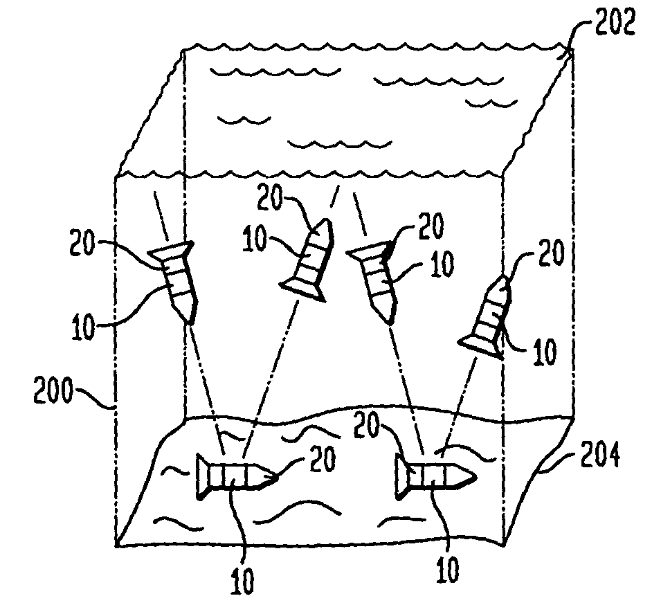
Underwater power generation using underwater thermocline

a technology of thermocline and power generation, applied in the direction of auxillary drives of vessels, special-purpose vessels, vessel construction, etc., can solve the problem of limited battery life of underwater missions, and achieve the effect of increasing the efficiency of power generation

Inactive Publication Date: 2007-08-28
THE UNITED STATES OF AMERICA AS REPRESENTED BY THE SECRETARY OF THE NAVY
View PDF5 Cites 25 Cited by
  • Summary
  • Abstract
  • Description
  • Claims
  • Application Information

AI Technical Summary

Benefits of technology

[0006]Other objects and advantages of the present invention will become more obvious hereinafter in the specification and drawings.
[0007]In accordance with the present invention, power generation is provided for an underwater vessel that transits through an underwater thermocline. At least a portion of a shell of an underwater vessel is made from a thermally conductive material. The portion of the shell has an outer surface in contact with a surrounding underwater environment and a dry inner surface opposing the outer surface. One or more thermo-to-electric energy converters are placed in contact with the inner surface of the shell. Hence, whenever heat energy flows into or out of the vessel through the energy converter, electrical power will be ...

Problems solved by technology

Therefore, the duration of an underwater mission powered by batteries is limited by t...

Method used


Image

  • Underwater power generation using underwater thermocline
  • Underwater power generation using underwater thermocline

Examples


Embodiment Construction

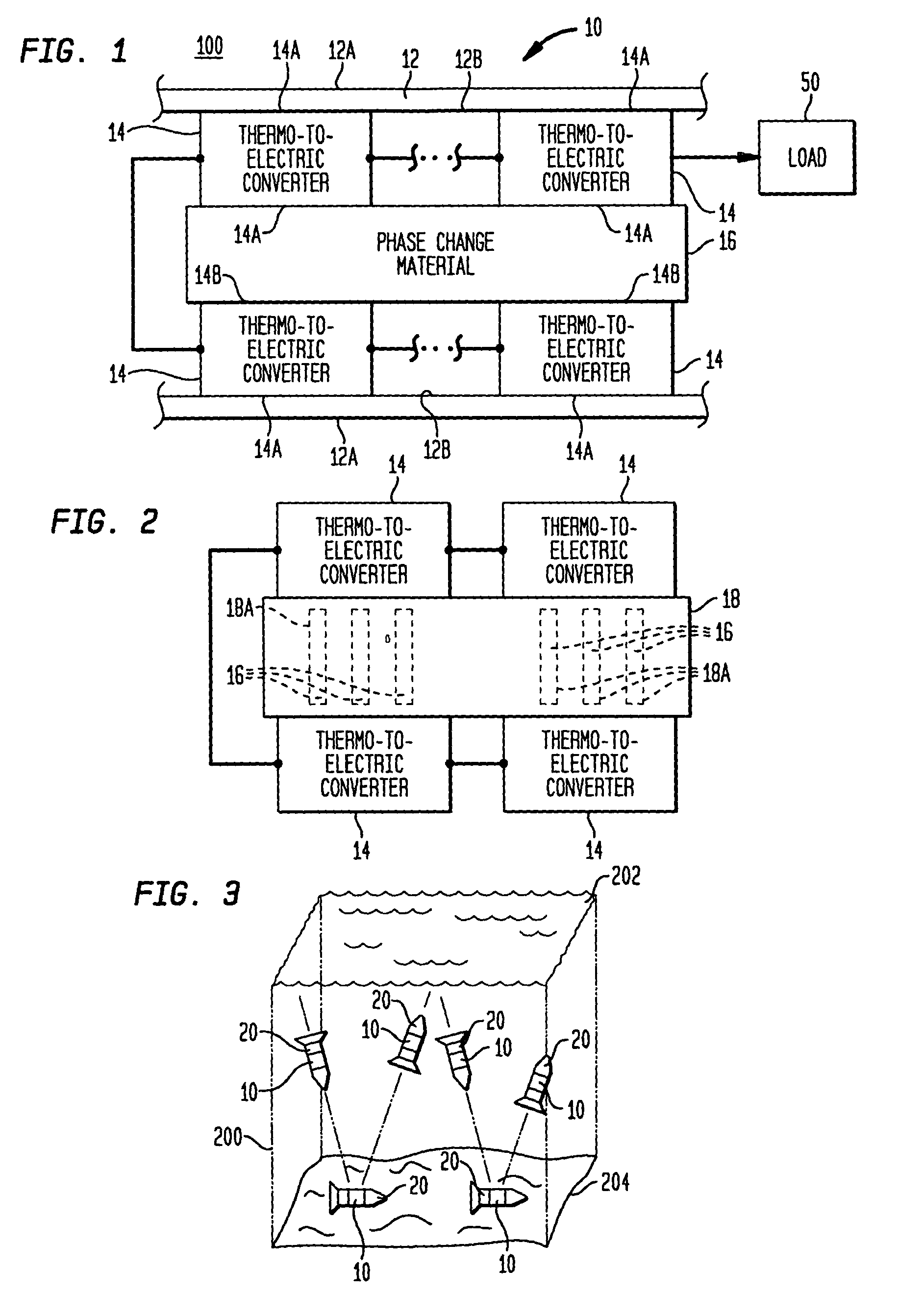
[0012]Referring now to the drawings, and more particularly to FIG. 1, an underwater power generator in accordance with the present invention is shown and is referenced generally by number 10. Typically, power generator 10 will be incorporated into a manned or unmanned navigating underwater vessel (not shown in FIG. 1) for the purpose of supplying electrical power for the vessel.

[0013]Power generator 10 is contained within a thermally-conductive shell 12 which can also form a portion of the underwater vessel in which power generator 10 is incorporated. Shell 12 is any thermally conductive material that efficiently conducts thermal energy, protects the elements of power generator 10 contained therein, and can withstand the rigors of underwater environments to include substantial operating depths on the order of 1000 meters or more. Suitable materials include aluminum and steel among others. The outer surface 12A of shell 12 will be exposed to an underwater environment 100 while the in...


PUM


Abstract

Underwater power generation for an underwater vessel is provided when the vessel transits through an underwater thermocline. At least a portion of the shell of the vessel is made from a thermally conductive material. Thermo-to-electric energy converters are electrically coupled together with each converter having a first surface thermally coupled to the shell's inner surface. A phase change material is thermally coupled to each opposing second surface of the converters. The phase change material has a phase change temperature that is between the upper and lower temperature extremes of the underwater thermocline's temperature range. The converters generate electrical power as the underwater vessel transits through the underwater thermocline.

Description

ORIGIN OF THE INVENTION[0001]The invention described herein was made in the performance of official duties by an employee of the Department of the Navy and may be manufactured, used, licensed by or for the Government for any governmental purpose without payment of any royalties thereon.FIELD OF THE INVENTION[0002]The invention relates generally to underwater power generation, and more particularly to a method and system for underwater power generation in which power is generated as an underwater vessel transits an underwater thermocline.BACKGROUND OF THE INVENTION[0003]Power for some military and civilian underwater vehicles is currently supplied by onboard batteries which have a fixed amount of energy available. Therefore, the duration of an underwater mission powered by batteries is limited by the storage capability of the batteries and the rate of power consumption during the mission.SUMMARY OF THE INVENTION[0004]Accordingly, it is an object of the present invention to provide a ...

Claims


Application Information

Patent Timeline
IPC IPC(8): H01L35/30
CPCB63H19/00B63J3/04H01L35/30B63B2035/4433B63B2035/4466B63G2008/004H10N10/13
Inventor DAVIS, PHILIP
Owner THE UNITED STATES OF AMERICA AS REPRESENTED BY THE SECRETARY OF THE NAVY
Why Eureka
Try Eureka