Display data mapping method, system, and program product

a display data and mapping technology, applied in the field of mapping display data, can solve the problems of preventing many implementations from efficiently converting pixel data into a shared format, significant obstacle to creating collaboration products that can be used across platforms, and platform dependency, and achieve the effect of efficient mapping

Inactive Publication Date: 2007-08-21
IBM CORP
View PDF11 Cites 11 Cited by
  • Summary
  • Abstract
  • Description
  • Claims
  • Application Information

AI Technical Summary

Benefits of technology

[0010]The invention provides a display data mapping method, system, and program product. A hierarchy of nodes is generated that represents various windows and their respective attribute information relevant to the display area being mapped. Display data for the display area is obtained and efficiently mapped using the hierarchy of nodes. The mapped display data can then be used, for example, to implement collaboration between users at multiple systems. For example, an X Windows application can be shared without the need to modify where the application is run or the X server software. Further, the invention can allow a system to share display data with different types of systems (i.e., X Windows and Microsoft WINDOWS®).

Problems solved by technology

One problem with many current collaboration software products is their platform dependency.
This presents a significant obstacle to creating collaboration products that can be used across platforms.
However, several factors prevent many implementations from efficiently converting pixel data into a shared format.
Determining when an area of the display has been modified is another factor that prevents efficiently converting display data.
However, an X server does not provide an event that signals when an area of a display has been modified.
This limitation can degrade productivity when an application cannot be readily restarted.
However, the use of extensions severely limits the number of platforms on which this approach can be readily implemented.
Categorizing and mapping each pixel is another performance problem for XWindows based sharing approaches that seek to share display data using external functions (i.e., no proxies, just standard X11 protocol) when the various windows within the shared display area may use different display formats to represent the display data.
External approaches that attempt to address the use of different display formats fail to provide an efficient solution for mapping pixel data that takes advantage of the hierarchical relationship of windows.

Method used


Image

  • Display data mapping method, system, and program product
  • Display data mapping method, system, and program product
  • Display data mapping method, system, and program product

Examples


Embodiment Construction

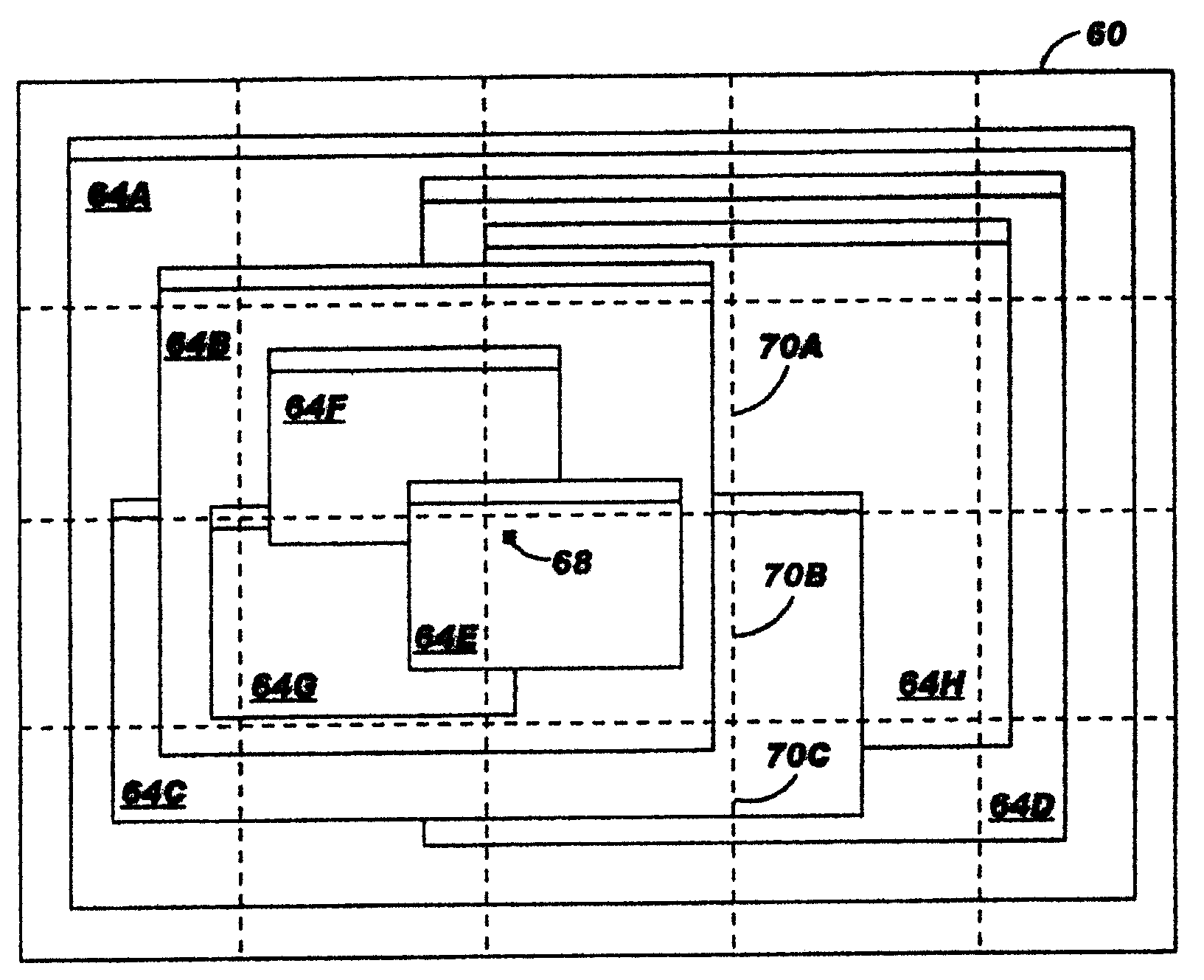
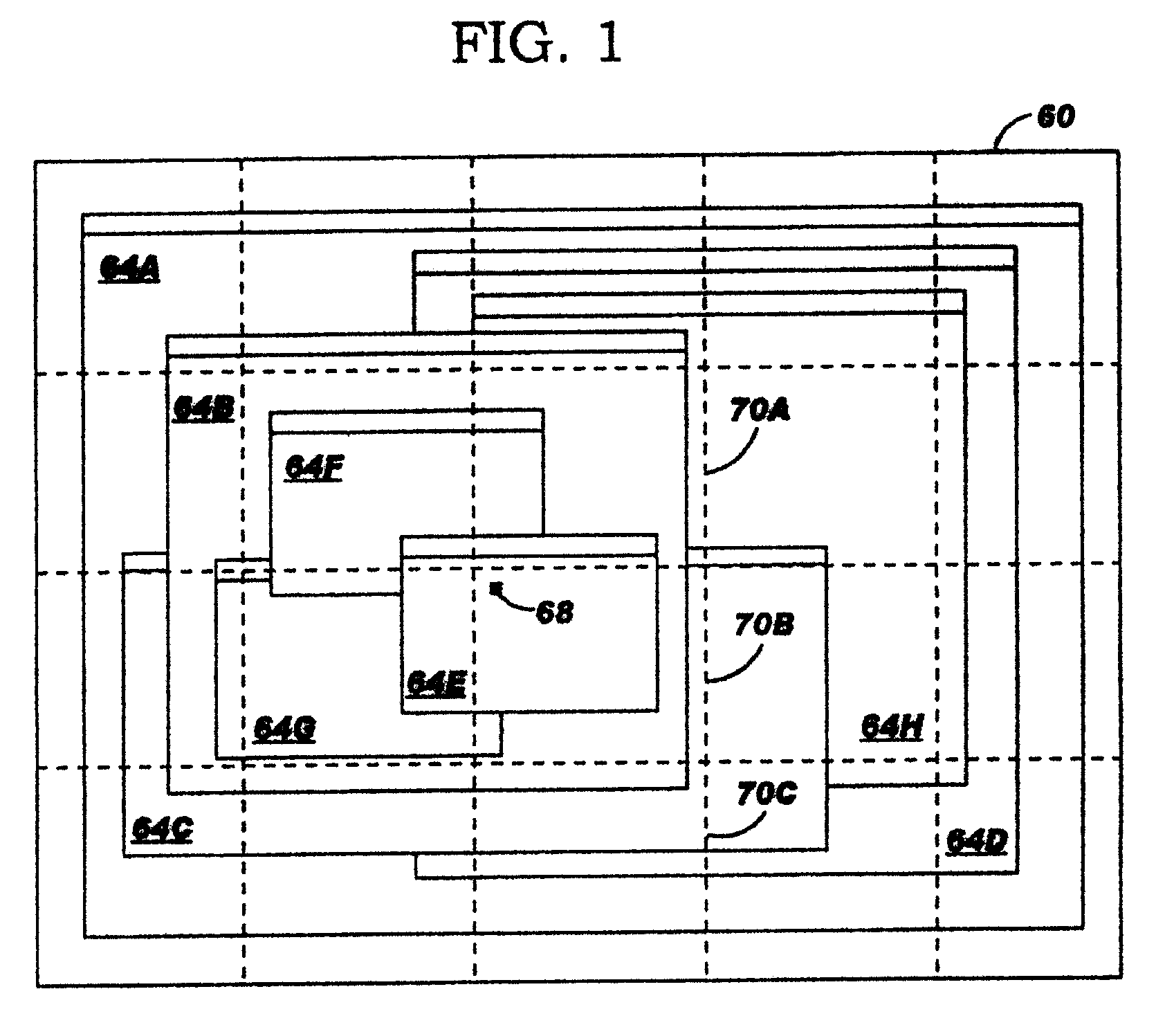
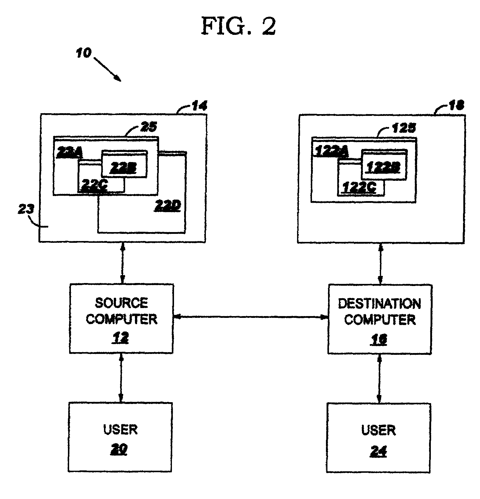
[0027]The invention provides a display data mapping method, system, and program product. A hierarchy of nodes is generated that represents various windows and their respective attribute information relevant to a display area being mapped. Display data for the display area is obtained and efficiently mapped using the hierarchy of nodes. The mapped display data can then be used, for example, to allow display data to be shared between users at multiple systems as part of a collaboration system. While the description below describes the invention implemented as part of a collaboration system, it is understood that the collaboration system is only illustrative of the various systems in which this invention can be implemented.

[0028]For convenience purposes only, the remaining description includes three sections denoted by the headings I. ENVIRONMENT, II. COLLABORATION SYSTEM OVERVIEW, III. MAPPING METHOD, and IV. MISCELLANEOUS.

[0029]I. Environment

[0030]FIG. 1 shows an illustrative display...


PUM


Abstract

A method, system, and program product are provided in which display data for a display area that includes at least one window is mapped to a shared format. Attribute information for each window in the display area is determined and stored in a unique node. A hierarchy of nodes is generated using the attribute information. For each pixel in the display area, the corresponding node is determined. Using the attribute information in the node, the display data is mapped to a shared format. The mapped display data can then be shared with one or more other systems.

Description

BACKGROUND OF INVENTION[0001]This invention generally relates to mapping display data, and more particularly to mapping display data from one or more formats to a shared format.[0002]Collaboration between individuals takes on many forms with face-to-face, telephone calls and e-mails being some of the most ubiquitous. As technology has progressed, individuals have sought to further collaborate by sharing video, voice, whiteboard markup, chat, as well as computer applications. Two common collaboration software products that allow such sharing are Lotus SAMETIME® and Microsoft NETMEETING®. One problem with many current collaboration software products is their platform dependency. For example, Microsoft NETMEETING® only works on systems that use a version of the Microsoft WINDOWS® operating system. Different platforms manage display data differently. This presents a significant obstacle to creating collaboration products that can be used across platforms.[0003]For example, display data ...

Claims


Application Information

Patent Timeline
Patent Type & Authority Patents(United States)
IPC IPC(8): G06F3/00G09G5/00G09G5/39
CPCG06F3/1454G06F9/4445G09G5/14G06F9/542G06F2209/544G06F2209/545G06F9/452G09G5/39G06F3/14
Inventor CRICHTON, JOSEPH M.
Owner IBM CORP
Why Eureka
Try Eureka