
Intensified structure for connecting a golf club head body with a striking plate

a golf club head and strengthening technology, applied in the field of strengthening structures for connecting golf club head bodies with striking plates, can solve the problems of weakening the entire structure affecting the connection reliability and the shoulder of the golf club head body only providing a limited volume within, so as to enhance the connection reliability, strengthen the connection structure, and strengthen the connection structure

Inactive Publication Date: 2007-08-21
FUSHENG IND CO LTD
View PDF11 Cites 56 Cited by
  • Summary
  • Abstract
  • Description
  • Claims
  • Application Information

AI Technical Summary

Benefits of technology

This intensified structure enhances the connection reliability and extends the useful life of the golf club head by securely filling the braze material within the connecting groove and preventing material outflow, thus reducing the risk of voids and cracks.

Problems solved by technology

However, the construction of the golf club head body has several drawbacks in the welding process.
Firstly, the shoulder of the golf club head body can only provide with a limited volume within the golf club head body and the striking plate for receiving the braze material.
Secondly, when the majority of the braze material is used to fill within a clearance between an inner peripheral wall of the assembling opening and an outer peripheral wall of the striking plate, spread in the welded portion between the golf club head body and the striking plate are caves and voids due to outflow of the braze material.
The caves and voids generated in the welding process may weaken the entire structure of the golf club head.
Inevitably, elastic deformations of the striking plate may generate an unwanted stress and thus cause cracks on the caves and voids spread in the welded portion between the golf club head body and the striking plate while striking golf.
Consequently, it may prolong the manufacture time and increase manufacture cost.

Method used


Image

  • Intensified structure for connecting a golf club head body with a striking plate
  • Intensified structure for connecting a golf club head body with a striking plate
  • Intensified structure for connecting a golf club head body with a striking plate

Examples


Embodiment Construction

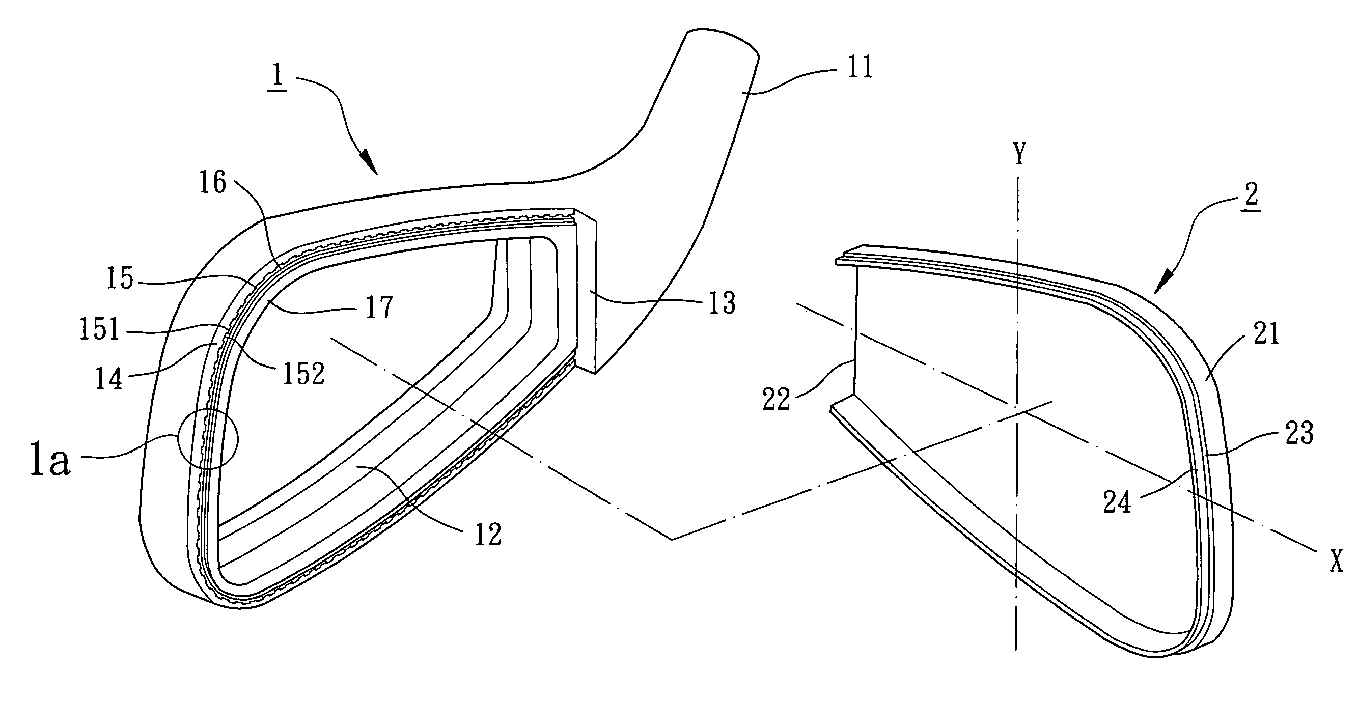
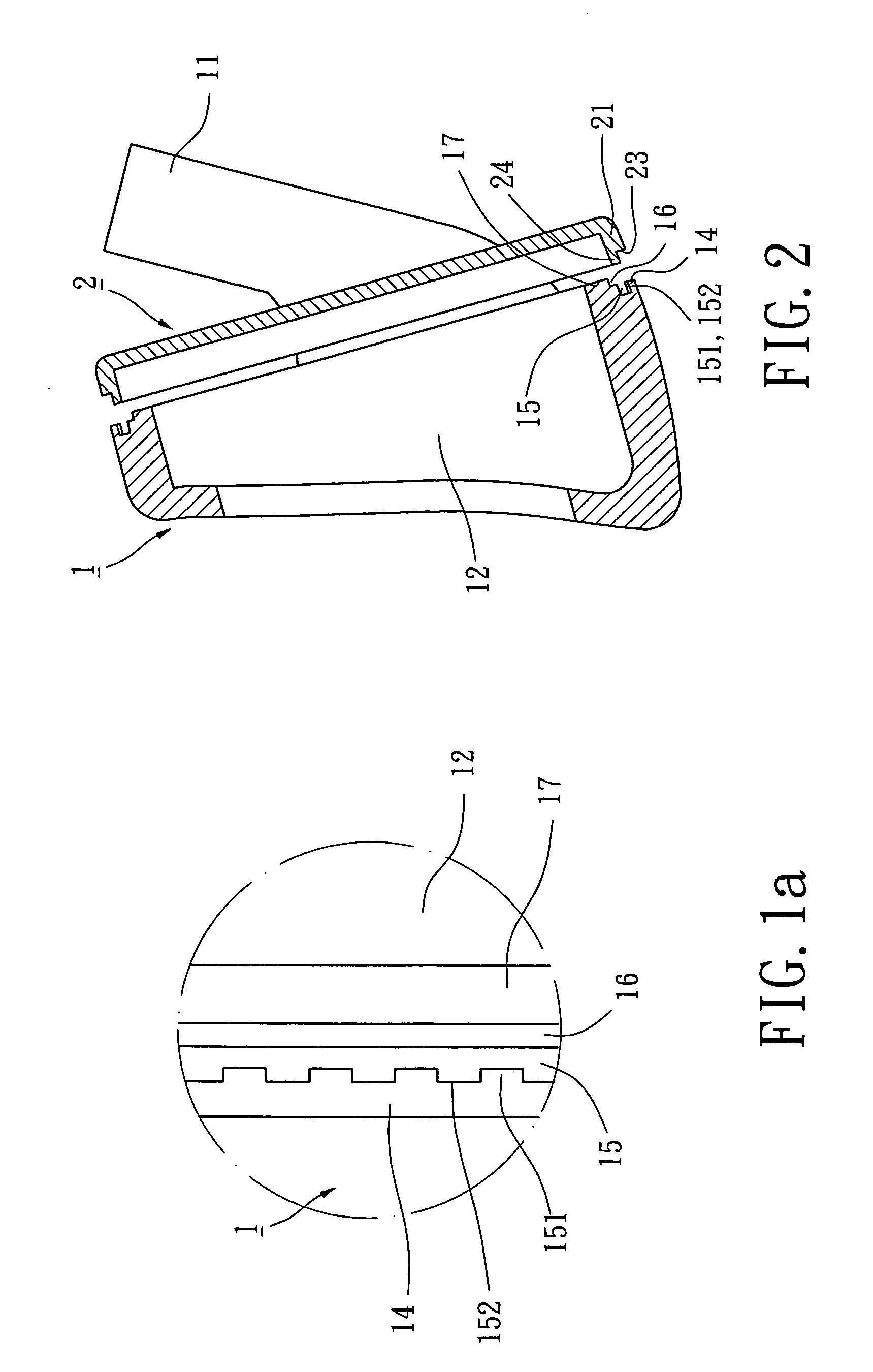
[0024]Referring initially to FIGS. 1, 1a and 2, a golf club head generally includes a golf club head body member designated numeral 1 and a striking plate member designated numeral 2. The golf club head can be selected from a group consisting of an iron-type club head, a wood-type club head and a putter-type club head. In the following embodiment, an intensified structure in accordance with the present invention shall be only applied to the iron-type and wood-type club heads. It will be understood that the intensified structure applied to the putter-type club head in accordance with the present invention is omitted.

[0025]Referring again to FIGS. 1, 1a and 2, the construction of the golf club head body 1 shall be described in detail. The golf club head body 1 is a monolithic shell including a hosel 11, an opening 12, a support wall 13, an engaging shoulder 14, a connecting groove 15, a filling space 16 and an annular lip 17. The hosel 11 is integrally connected or welded to the golf ...


PUM


Abstract

A golf club head includes a golf club head body having a connecting groove and a filling space, and a striking plate having an annular upright bent wall and a connecting end. In assembling, the connecting end of the annular upright bent wall of the striking plate is initially inserted into the connecting groove of the golf club head body so that an intensified structure is provided. The filling space of the golf club head body is further filled with a braze material. In brazing, the braze material contained in the filling space of the golf club head body is melted and thus filled within a clearance between the connecting groove of the golf club head body and the connecting end of the striking plate to form a welded layer.

Description

BACKGROUND OF THE INVENTION[0001]1. Field of the Invention[0002]The present invention relates to an intensified structure for connecting a golf club head body with a striking plate. More particularly, the present invention relates to the golf club head body having a connecting groove, a filling space and engaging protrusions for connecting a striking plate by means of press fitting, deformation engagement and brazing.[0003]2. Description of the Related Art[0004]U.S. Pat. No. 5,871,408, issued to CHEN on Feb. 16, 1999, discloses a manufacture method for connecting a golf club head body with a striking plate. The golf club head body and the striking plate are made of metal. The golf club head body includes an assembling opening and a shoulder formed therein for connecting the striking plate thereto. In assembling, the shoulder of the golf club head body is adapted to support a braze material. The striking plate is a flat faceplate engaged with the shoulder of the golf club head body b...

Claims


Application Information

Patent Timeline
Patent Type & Authority Patents(United States)
IPC IPC(8): A63B53/04
CPCA63B53/0466A63B53/047A63B2053/0416A63B53/0487A63B53/0416
Inventor HUANG, CHUN-YUNGCHEN, CHAN-TUNG
Owner FUSHENG IND CO LTD
Learn More