Eureka AIR delivers breakthrough ideas for toughest innovation challenges, trusted by R&D personnel around the world.

Tile spacer and leveler

Inactive Publication Date: 2007-08-21
KIRBY MARK E
View PDF6 Cites 223 Cited by
  • Summary
  • Abstract
  • Description
  • Claims
  • Application Information

AI Technical Summary

Benefits of technology

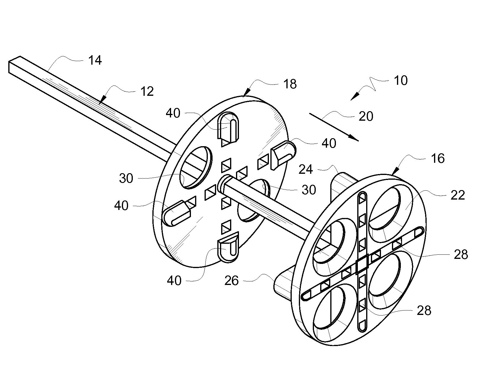
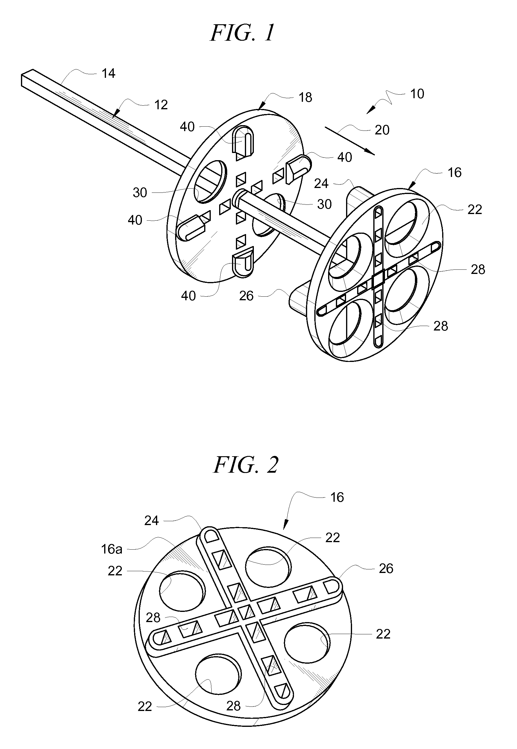
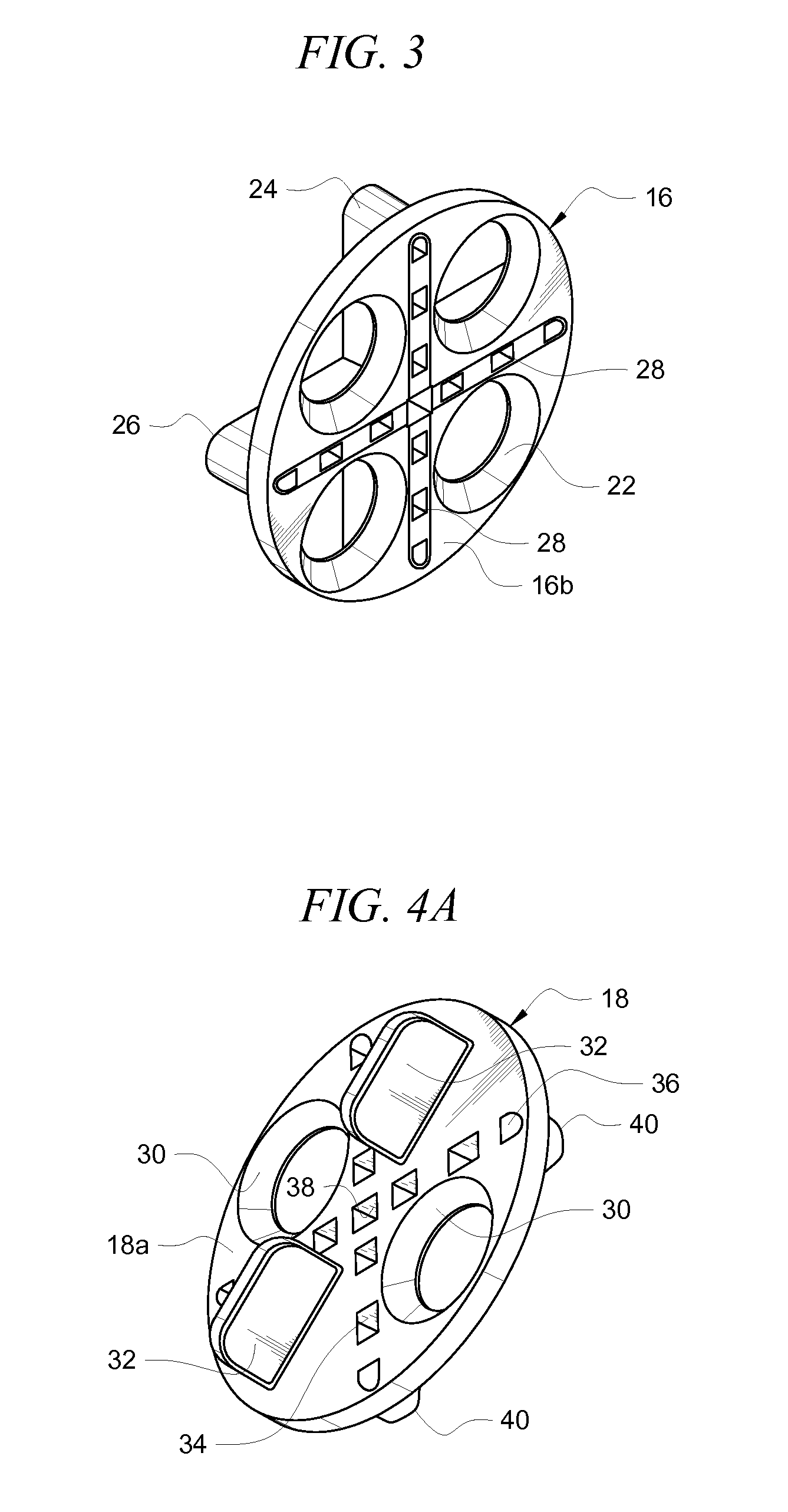
[0010]The first and second spacer arms intersect one another at a center of the top surface so that they share a common center. An opening is formed at said center to accommodate the leading end of the post that is formed integrally with said base. A plurality of equidistantly spaced openings is formed in each of the spacer arms along the respective extents thereof. These openings save materials and also admit cementitious material thereinto when the tiles are laid, thereby further securing the base to said cementitious material.

Problems solved by technology

Positioning a large plurality of tiles on a floor in such a way that all of the tiles are properly aligned and spaced apart from one another and level relative to one another when the job is complete is a difficult task.
Many tile installers fail, with the result that people trip over the upraised edges of non-level tile.
The difficulty arises primarily from the fact that the cementitious mixture upon which the tiles are laid requires a curing time of about twenty four (24) hours.
An installer might install the tiles in a level manner, and hold them for a while in an effort to ensure that they remain level as the cementitious material cures, but no one can manually hold the tiles overnight for the entire duration of the curing process.
Accordingly, as the cementitious material expands, or contracts, and settles during the curing process, the final position of the tiles may be uneven.
Spacing the tiles apart from one another is also problematic.
Such a tool would lower the skill level required to install tile.

Method used


Image

  • Tile spacer and leveler
  • Tile spacer and leveler
  • Tile spacer and leveler

Examples


Embodiment Construction

[0028]Referring now to FIG. 1, it will there be seen that a preferred embodiment of the invention is denoted as a whole by the reference numeral 10. Elongate straight post 12 has a plurality of small, very closely spaced ratchet teeth 14 formed therein along its length. Such ratchet teeth 14 are commonly found in flexible plastic ties where a pawl easily slides in a first direction relative to said teeth but cannot slide in a second direction that is opposite to said first direction. Such ties have numerous applications and are even used by police forces as handcuffs because they require no key-controlled lock. Post 12, however, is not flexible.

[0029]The lower end of post 14 is formed integrally with disc-shaped base 16 at the center of said base.

[0030]Movable top disc 18 is centrally apertured and a pawl means is formed in sidewalls of said central aperture to slidingly engage ratchet teeth 14 so that top disc 18 can be displaced in a first direction toward base 16 as indicated by ...


PUM


Abstract

A method for installing tiles includes the steps of positioning a base in overlying relation to cementitious material. First and second spacer arms are formed on the base in normal relation to one another. Preselected corners of four tiles are positioned in overlying relation to the base and are spaced apart from one another by the spacer arms. A post having ratchet teeth is formed integrally with the base at the center of the base. A disc receives the post and a pawl formed in the disc prevents displacement of the disc away from the base. The disc is positioned in overlying relation to the four corners of the tiles so that it overlies and holds the tiles level between the base and the disc. After curing of the cementitious material, an installer twists the disc in a plane parallel to the tiles until the post breaks off.

Description

BACKGROUND OF THE INVENTION[0001]1. Field of the Invention[0002]This invention relates to methods for installing tile. More particularly, it relates to a tool that ensures that all tiles used in an installation will be properly spaced apart from one another and level with one another.[0003]2. Description of the Prior Art[0004]Positioning a large plurality of tiles on a floor in such a way that all of the tiles are properly aligned and spaced apart from one another and level relative to one another when the job is complete is a difficult task. Many tile installers fail, with the result that people trip over the upraised edges of non-level tile. The difficulty arises primarily from the fact that the cementitious mixture upon which the tiles are laid requires a curing time of about twenty four (24) hours. An installer might install the tiles in a level manner, and hold them for a while in an effort to ensure that they remain level as the cementitious material cures, but no one can manu...

Claims


Application Information

Patent Timeline
IPC IPC(8): E04B9/00E04B1/00E04D15/00E04F21/00E04G21/00E04G21/14E04G23/00G01B1/00
CPCE04F15/02005E04F21/0092E04F21/22E04F15/02022
Inventor KIRBY, MARK E.
Owner KIRBY MARK E
Why Eureka
Eureka Blog
Learn More