
Through tubing real time downhole wireless gauge

a wireless gauge and through tubing technology, applied in the field of oil field communication and telemetry systems, can solve the problems of laborious, time-consuming and expensive, and the inability to maintain optimal flow rates, and achieve the effect of laborious, time-consuming and expensive, and pulling the entire length of production tubing out of the casing

Active Publication Date: 2007-08-14
SHELL USA INC
View PDF23 Cites 48 Cited by
  • Summary
  • Abstract
  • Description
  • Claims
  • Application Information

AI Technical Summary

Benefits of technology

The present invention is a system for transmitting data from a wellbore to the surface using electronics, sensors, and acoustic generators. The system includes a gauge that is inserted into a pipe and has an acoustic wave generator and a coupler that can be engaged with the pipe to define an acoustic transmission path. The system also includes a surface system with an acoustic wave generator and a coupler that can be engaged with the pipe. The method involves running the gauge into the pipe and setting it in place to communicate an acoustic signal between the gauge and the pipe. The technical effects of the invention include improved data transmission and reduced costs compared to traditional methods.

Problems solved by technology

For example, with gravel-packed production systems, perforations become clogged over time, so that optimum flow rates are not maintained.
This task is laborious, time-consuming and expensive.
Similar issues arise from artificial lift optimization, reservoir pressure monitoring, etc.
As noted above, it is laborious, time-consuming and expensive to pull the entire length of production tubing out of the casing to service and re-install a downhole control system.

Method used


Image

  • Through tubing real time downhole wireless gauge
  • Through tubing real time downhole wireless gauge
  • Through tubing real time downhole wireless gauge

Examples


Embodiment Construction

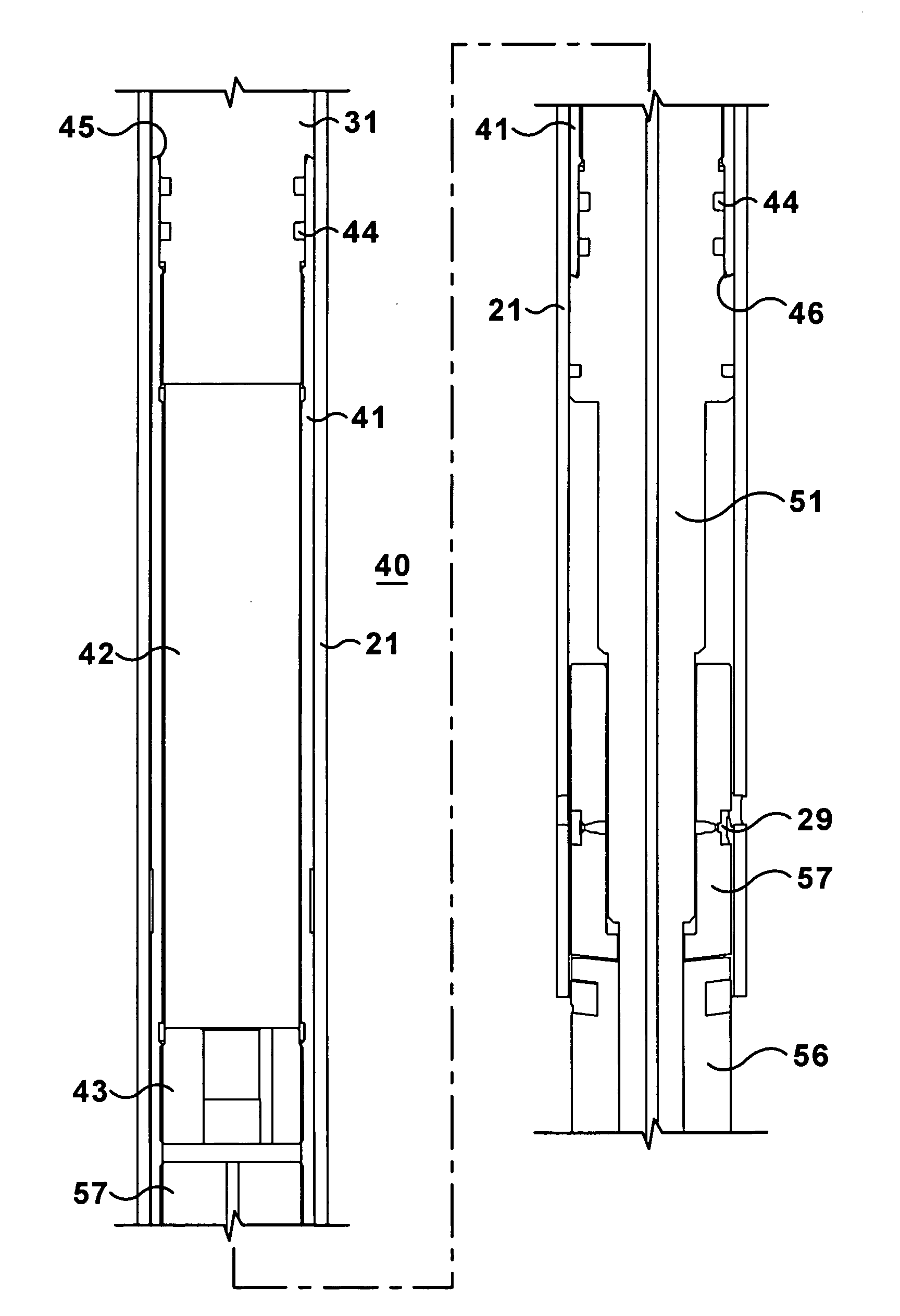
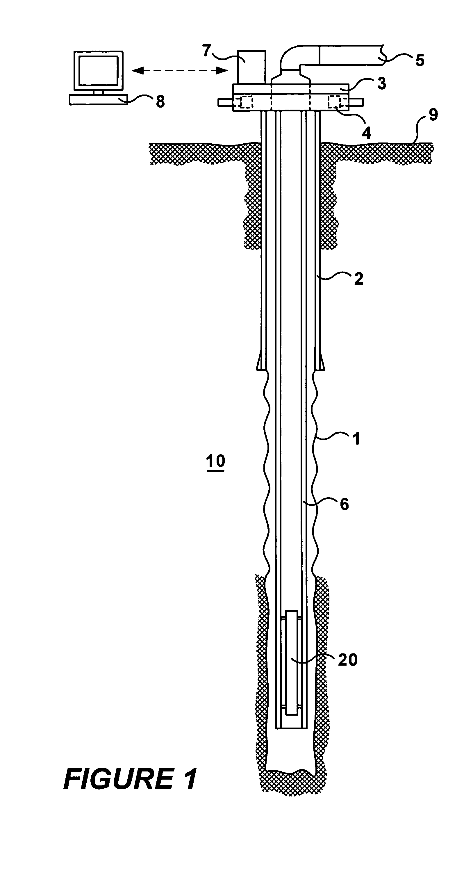
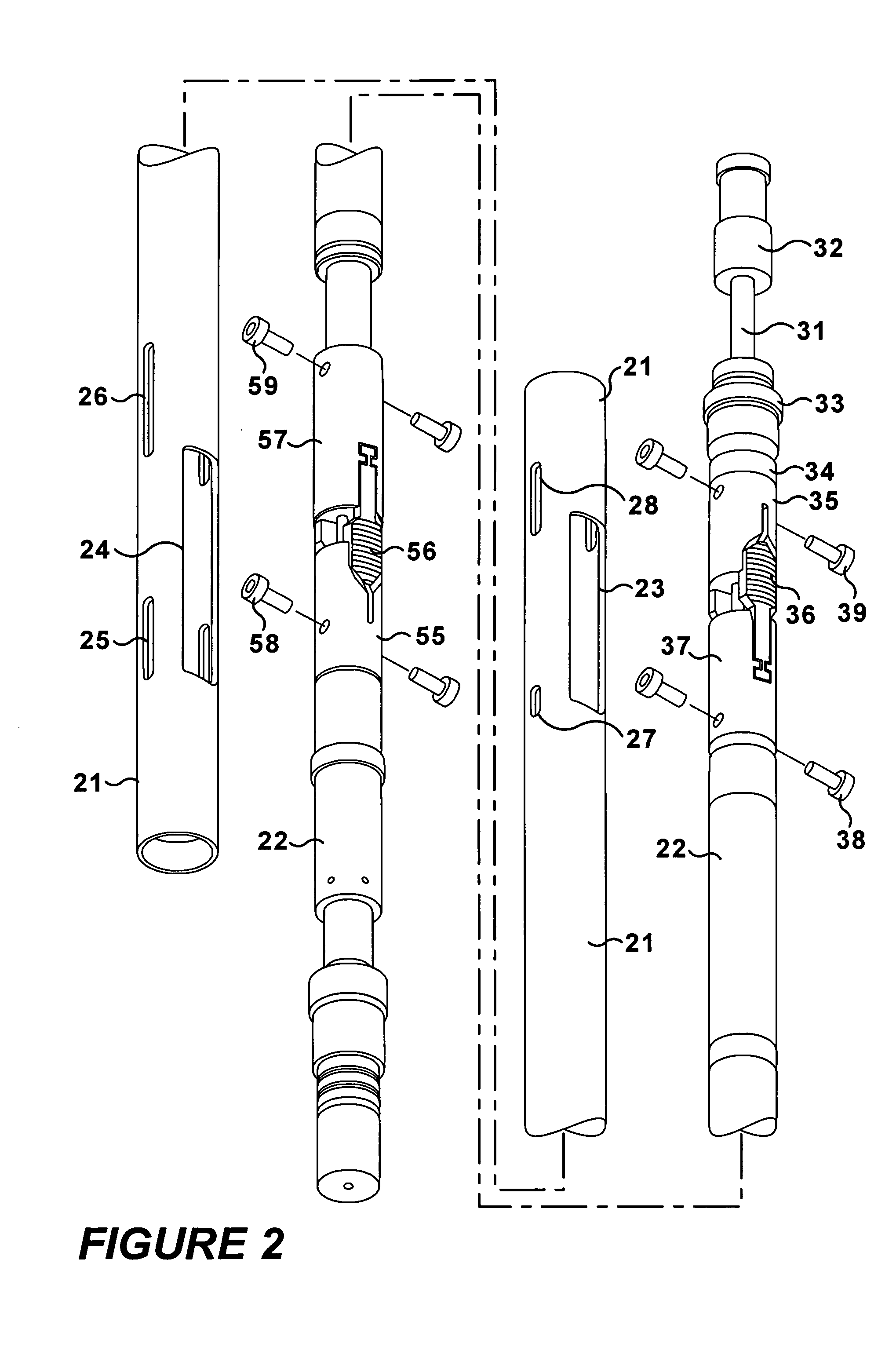
[0023]Referring to FIG. 1, a cross-sectional side view of a mineral production well is shown. A wireless wellbore digital data communications and sensing system (wireless telemetry system 10) of the present invention communicates through a production pipe 6 using compressional stress waves to transmit digital data from inside a wellbore 1 to the surface 9. The system is composed of wireless transmission hardware, acoustic generator, microprocessor system for data acquisition, processing and power management, pressure and temperature gauges, a battery pack unit and a surface receiver / transmitter box 7 for surface data acquisition and processing. A description of the basic system, surface module and communications is disclosed in patent application Ser. No. 10 / 381,766, incorporated herein by reference. The surface receiver / transmitter box 7 may operate using SCADA software. The acoustic waves travel up the production pipe 6 to the surface 9 in a compression mode minimizing losses rela...


PUM


Abstract

A telemetry system having: a pipe; a SCADA box acoustically coupled to the pipe; and a gauge inserted in the pipe, the gauge comprising: an acoustic wave generator; a coupler mechanically connected to the acoustic wave generator, wherein the coupler is engageable and disengageable with the pipe, wherein the coupler defines an acoustic transmission path between the acoustic wave generator and the pipe when engaged with the pipe; and a signal controller in communication with the acoustic wave generator. A method for communicating information in a wellbore from a downhole location to the surface, the method having the following steps: running a downhole gauge into a pipe within the wellbore, wherein the downhole gauge comprise an acoustic wave generator; setting the downhole gauge in the pipe; and communicating an acoustic signal between the downhole gauge and the pipe.

Description

FIELD OF THE INVENTION[0001]The present invention relates to oil field communication and telemetry systems. More particularly the invention relates to an acoustic wireless communications system through the production tubing.BACKGROUND OF THE INVENTION[0002]As new processes for drilling, completion, production, hydrocarbon enhancement, and reservoir management are developed, advancements in technologies related to temperature, pressure, and flow monitoring and downhole device control are required. Reservoir development systems must be constantly monitored to ensure maximum production. For example, with gravel-packed production systems, perforations become clogged over time, so that optimum flow rates are not maintained. To restore the production of the well, it has heretofore been a common practice to pull the entire length of production tubing out of the casing to clear the obstructed tubing perforations, or replace the perforated tubing section, and then re-install the production t...

Claims


Application Information

Patent Timeline
Patent Type & Authority Patents(United States)
IPC IPC(8): G01V3/00E21B47/16G01V1/00
CPCG01V1/005E21B47/16G01V1/52
Inventor STEWART, JOHNTUBEL, PAULBERGERON, CLARK J.
Owner SHELL USA INC
Learn More