Auto-aligning touch system and method

a touch system and auto-aligning technology, applied in the field of touch systems, can solve the problem of inconvenient execution of such an alignment routin

Active Publication Date: 2007-08-14
PIXART IMAGING INC
View PDF65 Cites 27 Cited by
  • Summary
  • Abstract
  • Description
  • Claims
  • Application Information

AI Technical Summary

Benefits of technology

The invention allows for the automatic mapping of an image to a touch screen in real-time without user intervention. This is achieved by analyzing captured image data to determine the displacement between known points in the image and the known co-ordinate system of the touch screen. This results in a more efficient and user-friendly experience for users interacting with the touch screen.

Problems solved by technology

The technical problem addressed in this patent is the inconvenience and annoyance of executing an alignment routine to map the co-ordinate system of a touch screen to the co-ordinate system of a computer display in touch systems where a standalone projector is used to project the computer-generated image on the touch surface. The patent aims to provide a novel auto-aligning touch system and method of automatically aligning a touch system to solve this problem.

Method used


Image

  • Auto-aligning touch system and method
  • Auto-aligning touch system and method
  • Auto-aligning touch system and method

Examples


Embodiment Construction

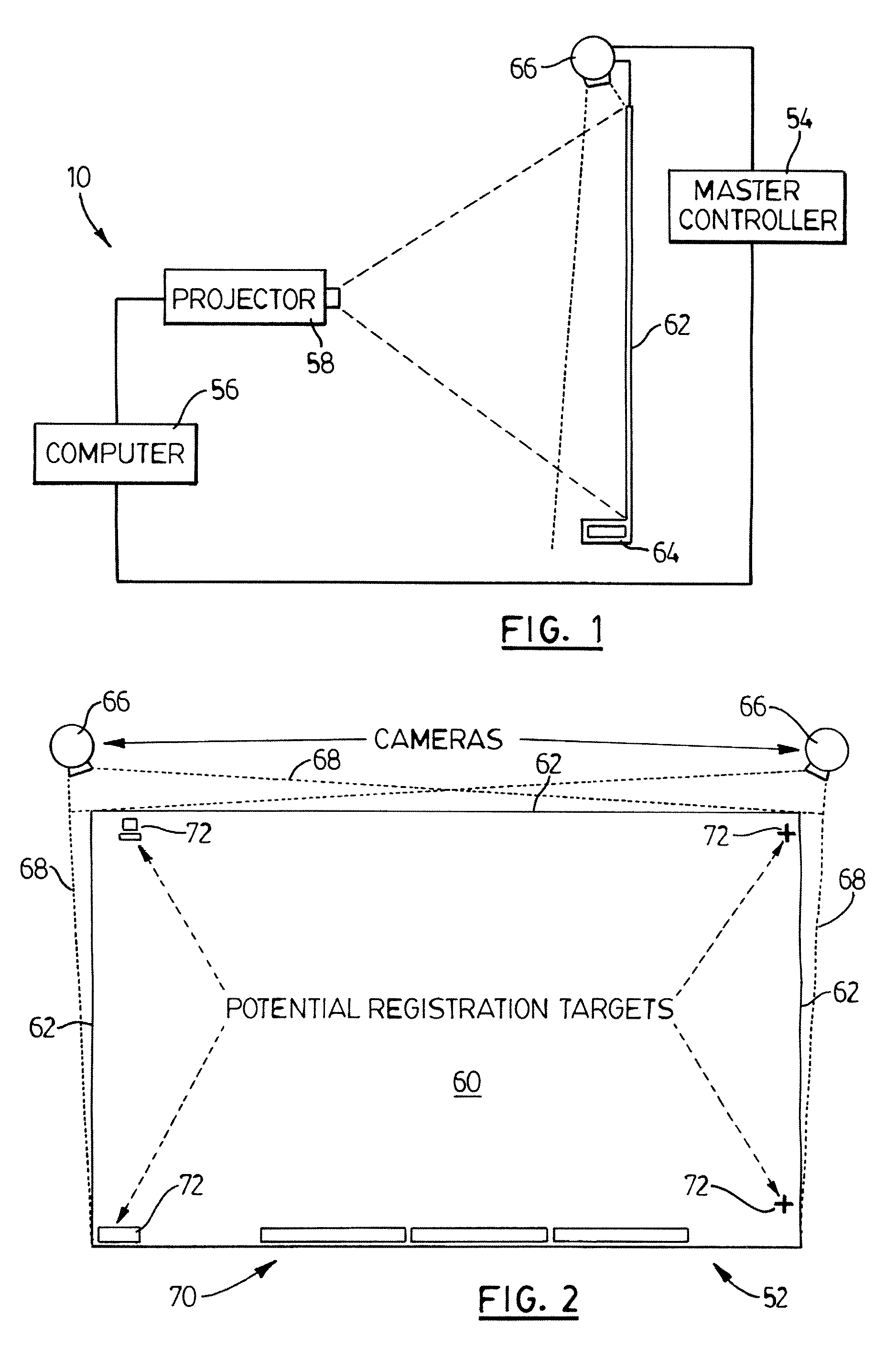
[0036]The present invention relates generally to a touch system and method that uses an acquired image of a touch surface on which an image having at least one known reference mark is presented, to calibrate automatically the touch system by mapping the touch screen co-ordinate system to the display co-ordinate system. As a result, the touch system can be calibrated in real-time as pointer contacts are made on the touch surface of the touch screen thereby to maintain high resolution and avoid the need to execute an alignment routine requiring manual intervention. The present invention is suitable for use in basically any application where a displayed image needs to be aligned with a touch surface such as for example, electronic whiteboards, touch liquid crystal display (LCD) panels, personal digital assistants (PDAs) and portable touch systems. Preferred embodiments of the present invention will now be described.

[0037]Turning now to FIGS. 1 and 2, a camera-based touch system in acco...


PUM


Abstract

A touch system includes a touch surface on which an image is, displayed and at least one camera acquiring images of the touch surface. A pointer contact data generator generates pointer position data in response to pointer contact with the touch surface. The pointer position data represents the location of the pointer on the touch surface where pointer contact is made. A processor communicates with the at least one camera and the pointer contact data generator. The processor uses known points in the displayed images to calibrate automatically co-ordinate systems of the touch system, and uses calibrated pointer position data to update image data that is used to present the displayed image on the touch surface. In one embodiment, the touch system includes an active touch sensitive screen that comprises both the touch surface and the pointer contact data generator. In another embodiment, image data generated by a pair of cameras having overlapping fields of view is used by the pointer contact data generator to generate the pointer position data when a pointer is acquired in images captured by the pair of cameras.

Description


Claims


Application Information

Patent Timeline
Owner PIXART IMAGING INC
Why Eureka
Try Eureka