Object positioning and display in virtual environments

Inactive Publication Date: 2006-05-09
TECHNION RES & DEV FOUND LTD
View PDF8 Cites 77 Cited by
  • Summary
  • Abstract
  • Description
  • Claims
  • Application Information

AI Technical Summary

Benefits of technology

[0018]It is a further aim of the present embodiments, to eliminate ambiguity in the relative position of virtual objects.
[0019]It is a further aim of the present embodiments, to enable virtual objects to be positioned correctly, and to enable 3D objects to be easily manipulated, in a meaningful way, according to the user's wishes, using a 2D projection.
[0020]It is a further aim of the present embodiments, to allow a first object to be easily placed in a desired position within a scene, such that all viewers, from all possible viewing angles, see the first object as being substantially in that desired position, thus overcoming the problem that the placing of an object within a 3D scene using 2D viewing is ambiguous.
[0022]It is a further aim of the present embodiments, to allow a first object to be easily placed in a desired position with respect to a second object within a scene, using standard devices commonly used for object manipulation, such as a computer mouse, for example.
[0023]It is a further aim of the present embodiments, to allow different users to interact according to different instructions, each according to prescribed limitations, which may either be predefined, or dynamically determined, or some combination thereof. These instructions need not be the same for each user.
[0024]It is a further aim of the present embodiments, to minimize the necessary data to be transferred to and from client terminals, after an application has been initiated, to enable the application to run smoothly in real-time.

Problems solved by technology

Computer graphics applications tend to be data heavy applications, comprising very large amounts of data.
3D environments, where changes of viewing position typically require redrawing of both the background and foreground objects displayed thereon are particularly data intensive.
In networked computing however, particularly with data-intensive, heavy applications, the speed at which applications run, is often limited by the time required for necessary data to be transferred between users on remote terminals, and / or between those remote terminals and the host computer.
Achieving real-time updating of high-resolution 3D graphical displays to a plurality of users is a challenging aim.
There is often a problem of positioning due to an ambiguity as to the true position of objects; that is at what depth into the scene objects are situated.
There is also an ambiguity as to relative depth of different objects.
In consequence, positioning objects correctly is not easy.
In virtual reality however, without stereoscopic display capability, perspective is merely an illusion, and it is difficult to tell which of two objects, placed in the foreground of a scene, is to be considered closer and which is to be considered further away from the viewer.
A further problem, which arises from the fact that the observer has only one viewpoint, is illustrated in FIGS. 3 and 4, representing different perspective viewpoints of a stack of blocks. FIG. 3 shows what appears to be a well-stacked tower of blocks as viewed from the front, whereas FIG. 4 shows the same scene from an alternative viewpoint, a few degrees in a clockwise direction, revealing that the bricks are not correctly stacked, as the user intended, but are rather staggered.
There are thus difficulties in navigating and positioning 3D objects in a virtual 3D scene, when viewing said scene on a 2D monitor.

Method used


Image

  • Object positioning and display in virtual environments
  • Object positioning and display in virtual environments
  • Object positioning and display in virtual environments

Examples


example

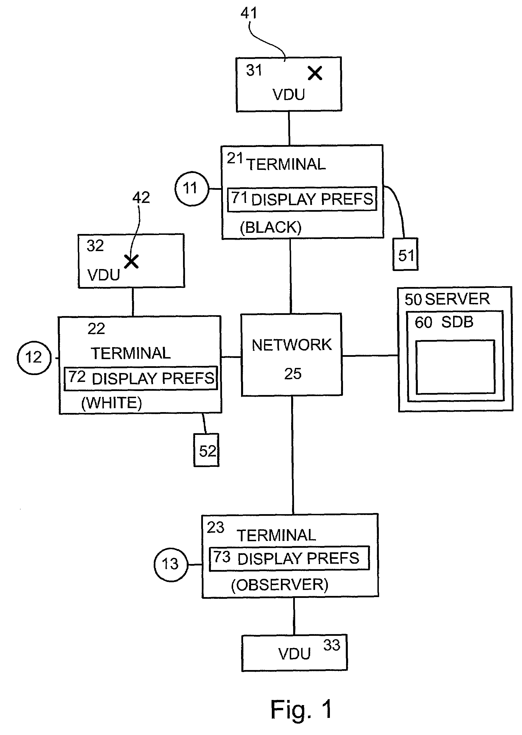
[0199]A preferred embodiment of the present invention comprises a distributed, real time and interactive three-dimensional system, the core of which is a memory resident, real-time, object-oriented database called the SDB (Scene Database). By incorporating the new features of ‘Functional Structuring for Networked Applications’, ‘object Positioning’, ‘Permissioning’, and the ‘Pop-up tool-tip menu’, it is possible to facilitate controlled multi-client interaction with 3D virtual reality applications, with the individual users using standard 2D input devices such as the computer mouse for interacting with the program.

[0200]A prototype of the preferred embodiment was, wherewith the 3D virtual reality was perceived on standard 2D computer monitors, and was also perceived using special immersive equipment. The scene database was implemented in C++ and enables a large number of users to interact with a number of objects therein. The SDB was further developed to allow the creation of new ob...


PUM


Abstract

A virtual environment for user interaction, and virtual objects for use therein, the virtual objects having an internal co-ordinate system with natural language definition to allow simplified inter-object relationships. The internal co-ordinate system is used to define docking positions for connecting to other objects to allow logical or natural positional relationships. A dynamically defined menu system allows pop-up menus for simple user entry of required relationships.

Description

RELATIONSHIP TO EXISTING APPLICATIONS[0001]The present application claims priority from U.S. Provisional Patent Application No. 60 / 233,487 filed Sep. 19, 2000.FIELD OF THE INVENTION[0002]The present invention relates to interaction with and positioning of virtual objects in virtual environments, and more particularly to permissible movements of Three Dimensional (hereinafter 3D) objects in 3D environments.BACKGROUND OF THE INVENTION[0003]Computer applications are often graphics based, and may; using what is commonly termed virtual reality, give an illusion of 3D space by situating virtual objects on a virtual 3D grid. Using immersion equipment, users can interact directly with this virtual environment. Additionally or alternatively, the 3D space can be projected on to a substantially flat or 2D surface such as a computer visual display unit (VDU), thus virtual reality may be viewed on substantially 2D computer screens, nevertheless, an illusion of solidity is maintained, and virtual...

Claims


Application Information

Patent Timeline
IPC IPC(8): G09G5/00G06T17/00
CPCG06T17/00
Inventor ELBER, GERSHONGERTELMAN, MICHAELSHAKED, ORITSHMUELI, ODED
Owner TECHNION RES & DEV FOUND LTD
Why Eureka
Try Eureka