
Wiper system using two wipers

a wiper and wiper technology, applied in the direction of starter details, dynamo-electric converter control, vehicle cleaning, etc., can solve the problems of large space in the center of the vehicle, requires additional requires more space in the hood, so as to avoid the collision of the wiper and reduce the cost and complexity. , the effect of less spa

Inactive Publication Date: 2007-08-14
ROBERT BOSCH GMBH
View PDF22 Cites 45 Cited by
  • Summary
  • Abstract
  • Description
  • Claims
  • Application Information

AI Technical Summary

Benefits of technology

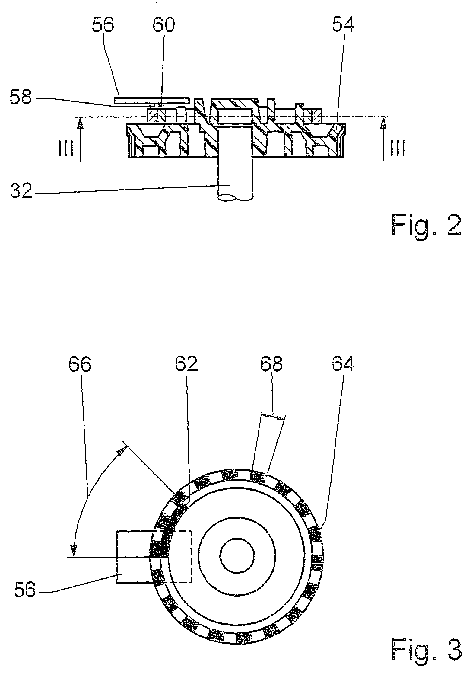
The present invention relates to a wiper system for vehicles that has two wiper motors. The first wiper motor is positioned on the driver side and operates in reversible operation. The second wiper motor is mounted on the passenger side and requires no separate electronic control unit. The second wiper motor is designed as a rotary motor with only one sensory system for detecting its position and speed. The control unit of the first wiper motor uses signals from the sensory system of the second wiper motor to regulate its position and speed. This design reduces the cost and complexity of the wiper system and makes it more efficient. The second wiper motor requires less space and has no separate electronic control unit. The system also includes a power switch and a sensory system for detecting the position of the second wiper motor. The second wiper motor may be a permanently energized three-brush direct-current motor with one gear step. The sensory system may have segmented permanent magnets and Hall sensors to detect the position and rotational speed of the second wiper motor. The system also includes a contact disk with sliding contacts to detect the position and speed of the second wiper motor. The technical effects of the invention include reducing the cost and complexity of the wiper system, making it more efficient, and avoiding collisions between the wipers.

Problems solved by technology

This leads to higher expenditures for the control device and requires additional space in the hood.
If these systems are driven by a wiper motor, a large size in accordance with the vehicle width results and a large space in the center of the vehicle.
Also, the kinematic design with or without intermediate bearing is complicated and necessitates a large, high-capacity wiper motor.

Method used


Image

  • Wiper system using two wipers
  • Wiper system using two wipers
  • Wiper system using two wipers

Examples


Embodiment Construction

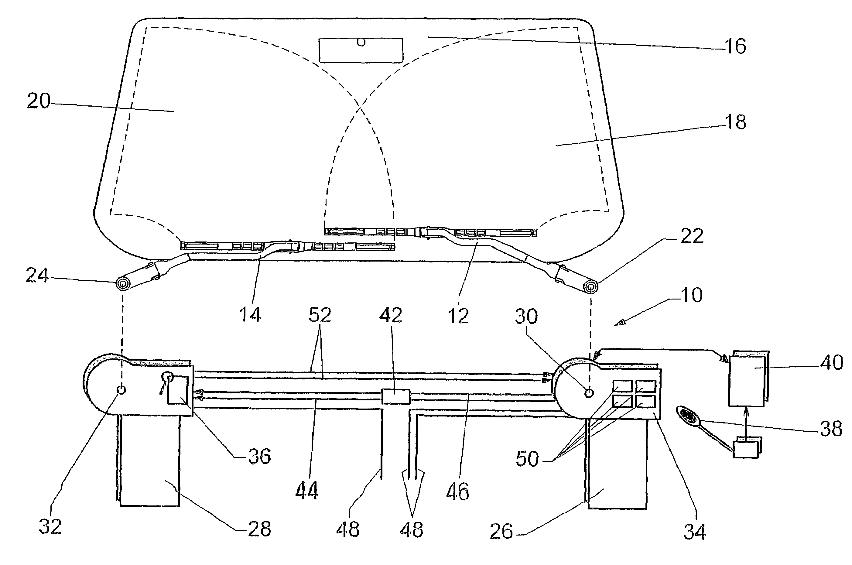
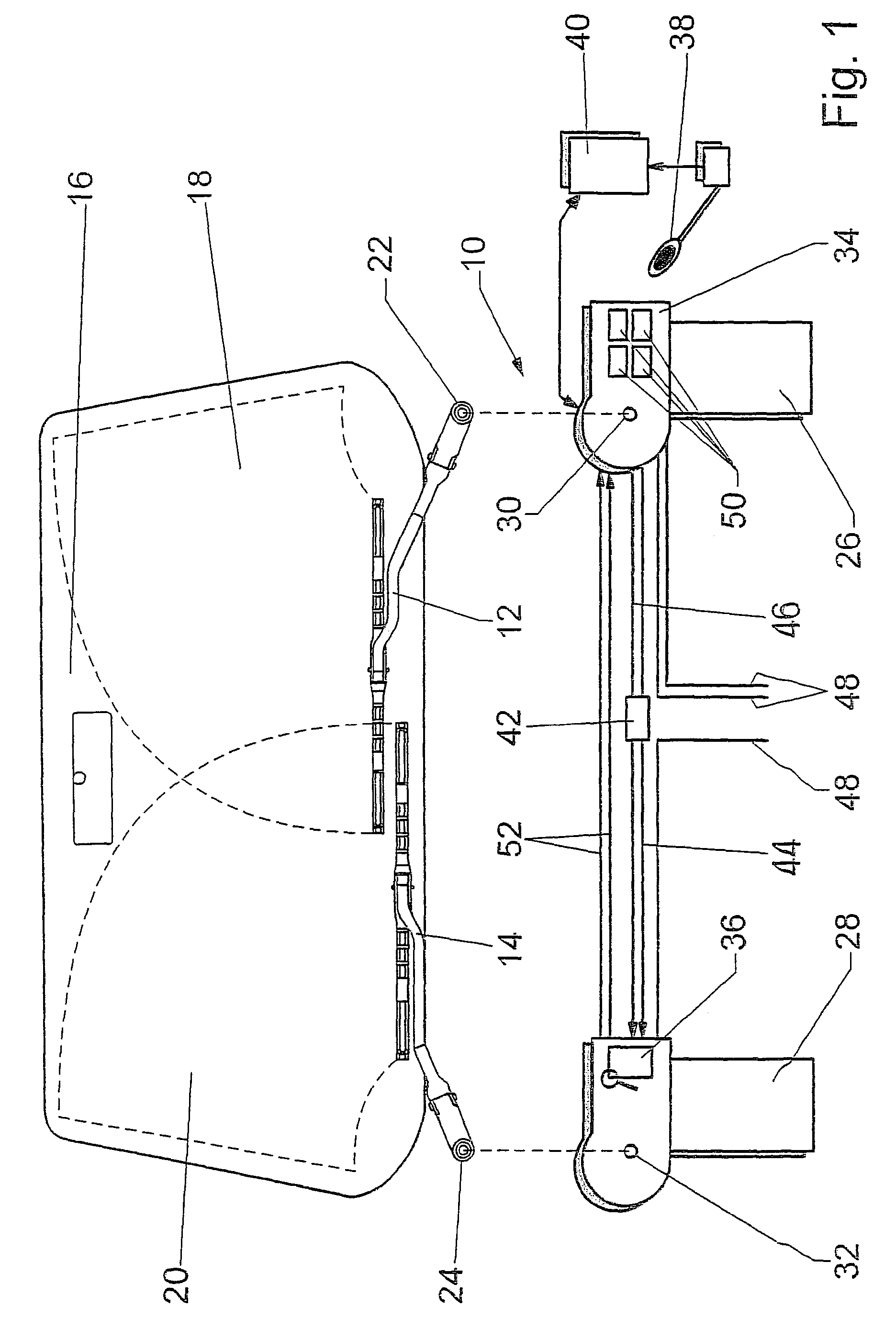
[0018]Wiper system 10 includes two wipers 12, 14, which sweep over wipe areas 18, 20 on a windshield 16 of a vehicle (not shown further) in the course of a swiveling motion about their drive shafts 22, 24.

[0019]A first wiper motor 26, via its driven shaft 30, drives drive shaft 22 of wiper 12 on the driver side of the vehicle, while a second wiper motor 28, by its driven shaft 32, drives drive shaft 24 of wiper 14 on the passenger side. First wiper motor 26, which is designed as reversing motor, has an electronic control unit 34 with control elements 50 to regulate the reversing operation and rotational speed as well as the rotational position of driven shaft 30 and, thereby, of wiper 12. Control elements 50 include means for analyzing the input signals and stored characteristics maps, and a sensory system 36 for detecting the rotational position and rotational speed of driven shaft 30, such as a micro-controller, an AMR sensor etc.

[0020]Second wiper motor 28, which is designed as a...


PUM


Abstract

A wiper system using two wipers and two wiper motors, which drive the wipers and of which at least one first wiper motor forms a sub-assembly with an electronic control unit. The second wiper motor is a rotary motor having only one sensory system for detecting the absolute and relative rotational position of its driven shaft, which generates corresponding signals for the control unit of the first wiper motor, and the first wiper motor, in the rotational speed and the rotational position of its driven shaft, is regulated by the control unit as a function of the rotational position and the rotational speed of the driven shaft of the second wiper motor.

Description

FIELD OF THE INVENTION[0001]The present invention relates to a wiper system using two wipers.BACKGROUND INFORMATION[0002]Different types of wipe areas and driving devices are known for cleaning windshields of motor vehicles. With respect to wipe areas, distinctions are mainly made between single-arm wipe areas and dual-arm wipe areas. In dual-arm wipe areas, the wiper arms of the wipers may be operated in tandem or in opposition.[0003]Even in the case of two wipers, the drive device generally uses only one wiper motor whose rotary drive movement of its driven shaft is translated into an oscillating swivel motion of the drive shafts of the wipers via a spatial crank drive. Newer wiper motors are provided with electronics which regulate a reversing drive movement of the driven shaft. The electronics also allow a control of the wipe angle including a dynamic, load-dependent wipe-angle correction and wiping-speed regulation, thereby producing a larger nominal wiped area on the windshiel...

Claims


Application Information

Patent Timeline
Patent Type & Authority Patents(United States)
IPC IPC(8): H02P5/00B60S1/08B60S1/28
CPCB60S1/0814Y10S318/02B60S1/08
Inventor MERKEL, WILFRIEDMICHENFELDER, GEBHARDFLEISCHER, CLAUS
Owner ROBERT BOSCH GMBH
Learn More