Multi-layer core golf ball
What is Al technical title?
Al technical title is built by PatSnap Al team. It summarizes the technical point description of the patent document.
a golf ball and multi-layer technology, applied in the field of golf balls, can solve the problems of low spin rate, low spin rate of two-piece golf balls, and generally difficult manufacture of golf balls, and achieve the effect of prolonging the usable life of golf balls
Inactive Publication Date: 2007-08-14
ACUSHNET CO
View PDF37 Cites 176 Cited by
Summary
Abstract
Description
Claims
Application Information
AI Technical Summary
This helps you quickly interpret patents by identifying the three key elements:
Problems solved by technology
Method used
Benefits of technology
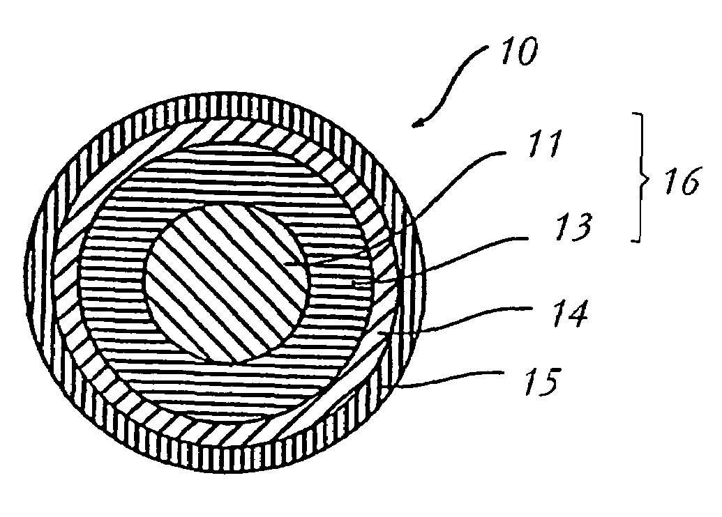
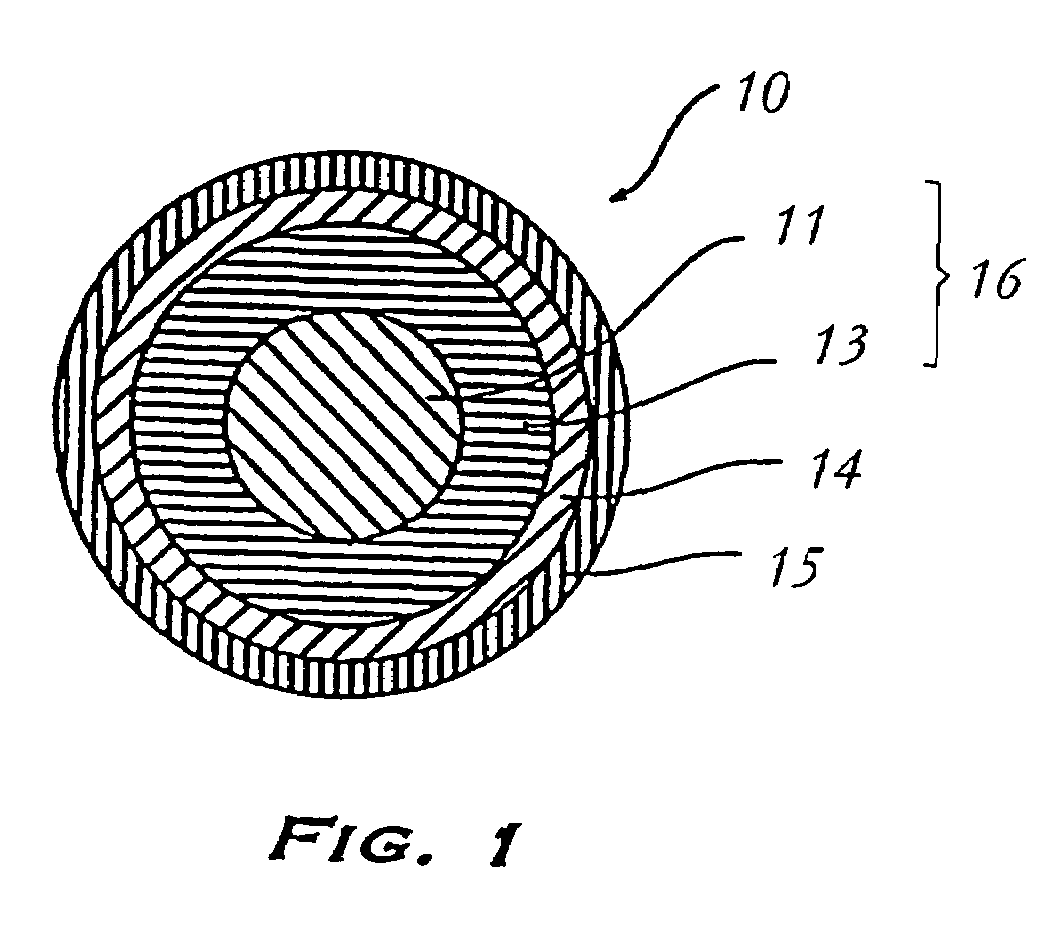
[0015]The golf ball can also include a moisture barrier layer disposed between the outer core layer and the cover layer. The moisture vapor barrier protects the inner and outer cores from degradation due to exposure to moisture, for example water, and extends the usable life of the golf ball. The moisture vapor transmission rate of the moisture barrier layer is selected to be less than the moisture vapor transmission rate of the cover layer. The moisture barrier layer has a specific gravity of from about 1.1 to about 1.2 and a thickness of less than about 0.03 inches. Suitable materials for the moisture barrier layer include a combination of a styrene block copolymer and a flaked metal, for example aluminum flake.
Problems solved by technology
However, wound balls are generally difficult to manufacture when compared to solid golf balls.
The stiffness and rigidity that provide the durability and improved distance, however, also produce a relatively low spin rate in these two piece golf balls.
Low spin rates make golf balls difficult to control, especially on shorter shots such as approach shots to greens.
Higher spin rates, although allowing a more skilled player to maximize control of the golf ball on the short approach shots, adversely affect driving distance for less skilled players.
For example, slicing and hooking the ball are constant obstacles for the lower skill level players.
Slicing and hooking result when an unintentional side spin is imparted on the ball as a result of not striking the ball squarely with the face of the golf club.
In addition to limiting the distance that the golf ball will travel, unintentional side spin reduces a player's control over the ball.
However, the addition of fillers may adversely interfere with the resiliency of the polymers used in golf balls and thereby the coefficient of restitution of the golf balls.
Method used
Image
Click on the blue label to locate the original text in one second.
Reading with bidirectional positioning of images and text.
Examples
Embodiment Construction
[0018]Referring to FIG. 1, golf ball 10 in accordance with the present invention is constructed to provide the desired spin profile and playing characteristics. In an embodiment as illustrated, golf ball 10 includes core 16 and cover layer 15 surrounding core 16. In one embodiment, the diameter of core 16 is greater than about 1.58 inches. Preferably, the diameter of core 16 is greater than about 1.6 inches. In one embodiment, the compression of core 16 is greater than about 50. In another embodiment, the compression of core 16 is greater than about 70. In yet another embodiment, the compression of core 16 is from about 80 to about 100.
[0019]As used herein, compression is measured by applying a spring-loaded force to the golf ball or golf ball component to be examined with a manual instrument (an “Atti gauge”) manufactured by the Atti Engineering Company of Union City, N.J. This machine, equipped with a Federal Dial Gauge, Model D81-C, employs a calibrated spring under a known load....
PUM
Property
Measurement
Unit
thickness
aaaaa
aaaaa
diameter
aaaaa
aaaaa
thickness
aaaaa
aaaaa
Abstract
The present invention is directed to an improved golf ball displaying the desired spin profile and having a generally rigid, thermoset polybutadiene outer core surrounding a relatively soft, low compression inner core. In general, this golf ball has an inner core and at least one outer core layer surrounding the inner core. The inner core has a hardness less than a hardness of the outer core and a specific gravity less than or equal to the outer core specific gravity. Overall the inner core compression and outer core are formulated to provide a combined overall core compression of greater than about 50, preferably greater than about 70. A cover layer is provided to surround and to cover the outer core layer. A moisture barrier layer is provided between the outer core layer and the cover layer to protect the inner and outer cores from degradation due to exposure to water. The moisture vapor transmission rate of the moisture barrier layer is selected to be less than the moisture vapor transmission rate of the cover layer.
Description
CROSS REFERENCE TO RELATED APPLICATIONS[0001]This application is a continuation-in-part of U.S. patent application Ser. No. 10 / 341,574, filed Jan. 13, 2003, now U.S. Pat. No. 6,852,044, which is a continuation-in-part of U.S. patent application Ser. No. 10 / 002,641, filed Nov. 28, 2001, now U.S. Pat. No. 6,547,677, which is a continuation-in-part of U.S. patent application Ser. No. 09 / 948,692, filed Sep. 10, 2001, which is a continuation-in-part of U.S. patent application Ser. No. 09 / 172,608, filed Oct. 15, 1998, now U.S. Pat. No. 6,302,808, which is a division of U.S. patent application Ser. No. 08 / 943,932, filed Oct. 3, 1997, now U.S. Pat. No. 6,056,842; the '641 application is also a continuation-in-part of U.S. patent application Ser. No. 08 / 996,718, filed Dec. 23, 1997, now U.S. Pat. No. 6,124,389, which is a continuation-in-part of U.S. patent application Ser. No. 08 / 746,362, filed Nov. 8, 1996, now U.S. Pat. No. 5,810,678, which is a continuation-in-part of U.S. patent applica...
Claims
Application Information
Patent Timeline
Application Date:The date an application was filed.
Publication Date:The date a patent or application was officially published.
First Publication Date:The earliest publication date of a patent with the same application number.
Issue Date:Publication date of the patent grant document.
PCT Entry Date:The Entry date of PCT National Phase.
Estimated Expiry Date:The statutory expiry date of a patent right according to the Patent Law, and it is the longest term of protection that the patent right can achieve without the termination of the patent right due to other reasons(Term extension factor has been taken into account ).
Invalid Date:Actual expiry date is based on effective date or publication date of legal transaction data of invalid patent.