
Lumbar support, cushion for seat, and seat structure

a technology for lumbar vertebrae and cushions, which is applied in the direction of adjustable chairs, chairs, transportation and packaging, etc., can solve the problems of increasing the number of times the cushion needs to be filled by pump, difficult to adjust the pump during driving, and air leakage during use, so as to suppress the nervous series between a third and fourth lumbar vertebrae, the effect of suppressing any sense of lack of conformity or unpleasantness feeling, and suppressing excessive pressur

Active Publication Date: 2007-08-14
DELTA TOOLING CO LTD
View PDF14 Cites 23 Cited by
  • Summary
  • Abstract
  • Description
  • Claims
  • Application Information

AI Technical Summary

Benefits of technology

[0010]The present invention has been made in view of the above problems and an object of the present invention is to provide a lumbar support which has two bulges (housing part), avoids exerting pressure on the nervous system between the third lumbar vertebra and the fourth lumbar vertebra, and is parallel to a curve of the back so that no feeling of a lack of conformity or no unpleasant is felt, and a cushion for a seat and a seat structure into which the lumbar support is incorporated. In addition, an object of the present invention is to provide a lumbar support which can easily adjust a cushioning feeling fitting to user's preference even when it is not an air cushion type, and a cushion for a seat and a seat structure incorporating such a lumbar support. Furthermore, when it is an air cushion type to fill air as a cushioning material for adjustment, an object of the present invention is to provide a lumbar support having a desired elasticity even if air leakage occurs and can exhibit a function as a lumbar support for a long time, and a cushion for a seat and a seat structure incorporating such a lumbar support.
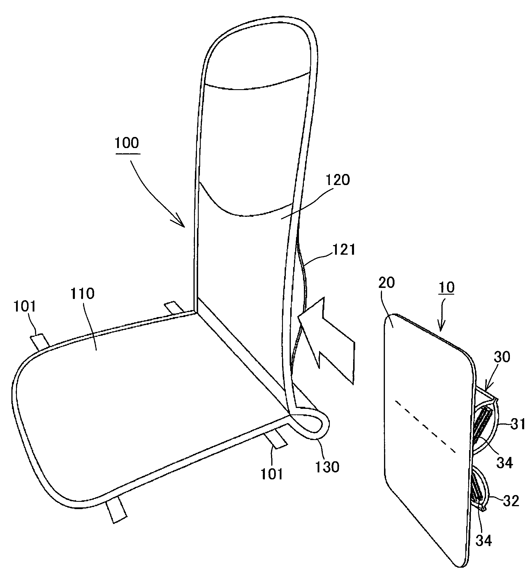
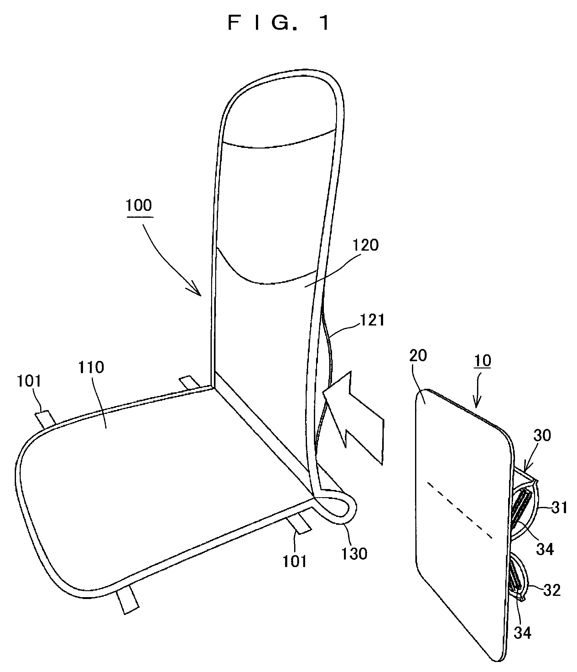
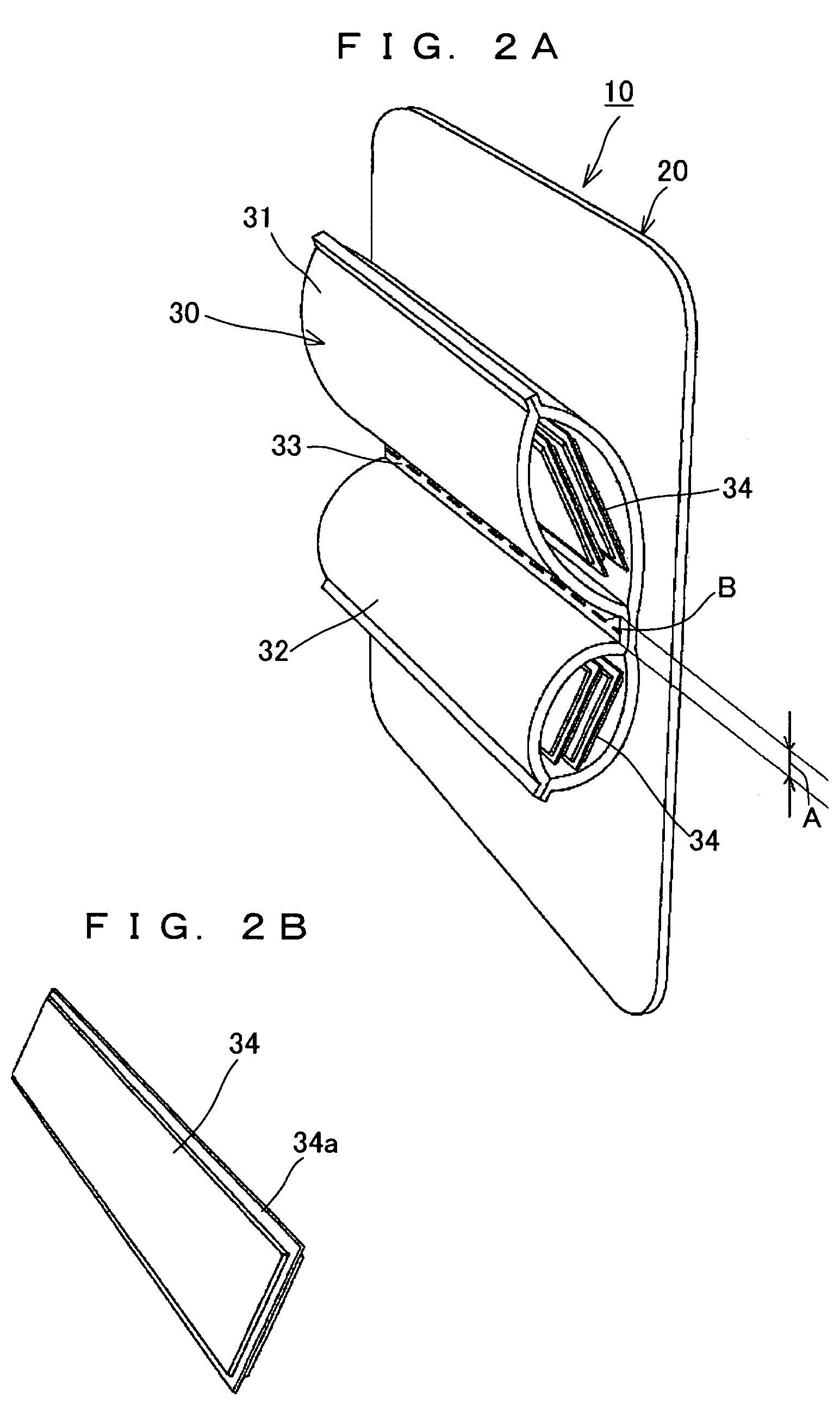
[0035]The lumbar support of the present invention is structured such that a bulging member provided with two housing parts to house a cushioning material for adjustment is fixed on the rear surface of the flexible plate, and the front surface of the flexible plate is positioned on the front surface of the back cushion. Accordingly, since the curvature of the two housing parts does not give a feeling of contact with the waist as it is, but acts as a feeling of contact with larger curvature by the flexible plate, pressure on the nervous series between a third and fourth lumbar vertebrae can be suppressed. Furthermore, by establishing the width of the border region between two housing parts to be within an appropriate range, it is possible to suppress any sense of lack of conformity or unpleasantness feeling due to there being too large a curvature as well as a feeling of excessive pressure on such nervous system.
[0036]The bulging member is not disposed independently in the back cushion, but is integrally formed with the flexible plate. Accordingly, by forming an insertion hole in a side portion of the back cushion, it is easily taken out or brought in while holding the flexible plate. As a result, for instance, by making the two housing parts in different sizes in advance, it is possible to easily place the larger housing part on the upper side or on the lower side to suit to user's preference. Furthermore, by adjusting the number of the cushioning materials for adjustment to be housed in each housing part, a minute adjustment becomes possible according to user's preference. Moreover, if a solid knitted fabric is used for a cushioning material for adjustment, high air permeability can be ensured. And if a stripped solid knitted fabric with edge treatment is used at that time, since an end treated periphery has a prescribed stiffness, which facilitates a loading work into the housing part and unloading work therefrom. When a structure having an air bag main body inside which a solid knitted fabric is housed, and air can be filled is used, since the elasticity of the solid knitted fabric is maintained even if air leakage occurs, it is fitted for a long usage without shortage of sense of supporting the human waist. In particular, since a desired elasticity is ensured by a solid knitted fabric without necessity of refilling air by pressurizing a pump even occurrence of air leakage, it is suitable to use as a lumbar support by incorporating it into a back cushion of a seat back on a driver's seat of a car seat or a back cushion of a cushion for a seat to be set on a car seat. Furthermore, by adjusting a filling amount of air, it is possible to let elasticity provided by air pressure and elasticity provided by a solid knitted fabric work synergistically, which makes it possible to variously adjust elasticity according to user's preference.

Problems solved by technology

However, no matter how airtight the bag and the connection tube, air still leaks gradually during use.
Therefore, the desired elasticity of the air cushion is difficult to obtain depending on the air leaked amount, and the cushion's function as a sufficient lumbar support to support the waist disappears at an early stage, resulting in an increase in the number of times the cushion needs to be refilled by pump.
Especially, on a driver's seat in a car, if the air cushion comes short of elasticity due to air leakage, it is extremely difficult to adjust the pump during driving.
In other words, since it is only a structure to be able to adjust the height of a lumbar support, it is impossible to adjust a feeling of cushioning unlike an air cushion type lumbar support disclosed in the Patent Document 1, and the like.
However, if curvature of the bulging portion is too small or too large, a feeling of a strong pressure contact or a sense of a lack of conformity is felt when coming into contact with the back (the waist).

Method used


Image

  • Lumbar support, cushion for seat, and seat structure
  • Lumbar support, cushion for seat, and seat structure
  • Lumbar support, cushion for seat, and seat structure

Examples


Embodiment Construction

)

[0058]The present invention will be further explained hereinafter based on embodiments of the present invention shown in the drawings. In the present embodiment, as shown in FIG. 1, a lumbar support 10 is loaded on a cushion for a seat 100 used while being fixed by a belt member or the like, placed on a seat cushion and a seat back of a seat structure for automobiles or the like.

[0059]As shown in FIG. 1, FIGS. 2A and 2B, the lumbar support 10 has an integrated structure of a flexible plate 20 and a bulging member 30. The flexible plate 20 is made of plastic such as, for instance, polypropylene. The flexible plate 20 has a size larger than the size of a border region 33 between two housing parts 31 and 32 forming the bulging member 30 to be described later, and disposed to make a radius of an arc to bulge a back cushion large, to prevent pressure on a nervous system between a third and fourth lumbar vertebrae, and to obtain a curvature similar to a curve of a human spiral column. Ac...


PUM


Abstract

In order to provide a lumbar support which conforms to the curve of the spinal column so as not to give a feeling of incompatibility or other unpleasant feeling, and is easily adjusted to meet a user's preference, a lumbar support 10 of the present invention is structured such that a bulging member 30 provided with two housing parts 31 and 32 to house a cushioning material for adjustment 34 is fixed on the back surface of a flexible plate 20, which is incorporated so that the front surface of the flexible plate 20 is positioned to the front surface side of a back cushion 120. Accordingly, the curvature of the two housing parts 31 and 32 does not affect a feeling of contact with the waist as it is, but works as a feeling of contact with larger curvature owing to the flexible plate 20, which results in suppression of pressure on the nervous system between the third and fourth lumbar vertebrae. Furthermore, by setting the width of a border region 33 between the two housing parts 31 and 32 in an appropriate range, it is possible to suppress a feeling of pressure on such a nervous system, and at the same time, to suppress any feeling of incompatibility or other unpleasant feeling caused by too large a curvature.

Description

BACKGROUND OF THE INVENTION[0001]1. Field of the Invention[0002]The present invention relates to a lumbar support suitably used for a cushion for a seat, which is used by being mounted in a seat structure for transportation machines such as an automobile, a plane, a train, a ship, a fork lift and the like, those seat cushion and a seat back, a cushion for a seat, into which the lumbar support is incorporated, and a seat structure into which the lumbar support is incorporated.[0003]2. Description of the Related Art[0004]In Patent Document 1, a back mat which is made by attaching a bag as an air cushion on a flat rubber mat base is disclosed. The back mat is used by fixing on a seat back of an office chair, a car seat, and the like with a belt member. It is also disclosed that the air cushion is provided at a position corresponding to the vicinity of a seated person's waist, and formation of an air cushion in a plurality of rooms to ensure air permeability. In Patent Document 2, discl...

Claims


Application Information

Patent Timeline
Patent Type & Authority Patents(United States)
IPC IPC(8): A47C7/46
CPCB60N2/66B60N2/665
Inventor OGURA, YUMI
Owner DELTA TOOLING CO LTD
Learn More