
Process fluid flow device with variable orifice

a technology of process fluid flow and orifice, which is applied in the direction of process and machine control, liquid/fluent solid measurement, instruments, etc., can solve the problems of additional process fluid seals that may fail, flow control systems that introduce additional costs, and control systems that require additional technician time for installation and/or maintenan

Active Publication Date: 2007-08-14
ROSEMOUNT INC
View PDF10 Cites 855 Cited by
  • Summary
  • Abstract
  • Description
  • Claims
  • Application Information

AI Technical Summary

Problems solved by technology

For example, each different device in the flow control system introduces additional costs as well as additional process fluid seals that may fail.
Further, each process device used in a flow control system will also require additional technician time for installation and / or maintenance.

Method used


Image

  • Process fluid flow device with variable orifice
  • Process fluid flow device with variable orifice
  • Process fluid flow device with variable orifice

Examples


Embodiment Construction

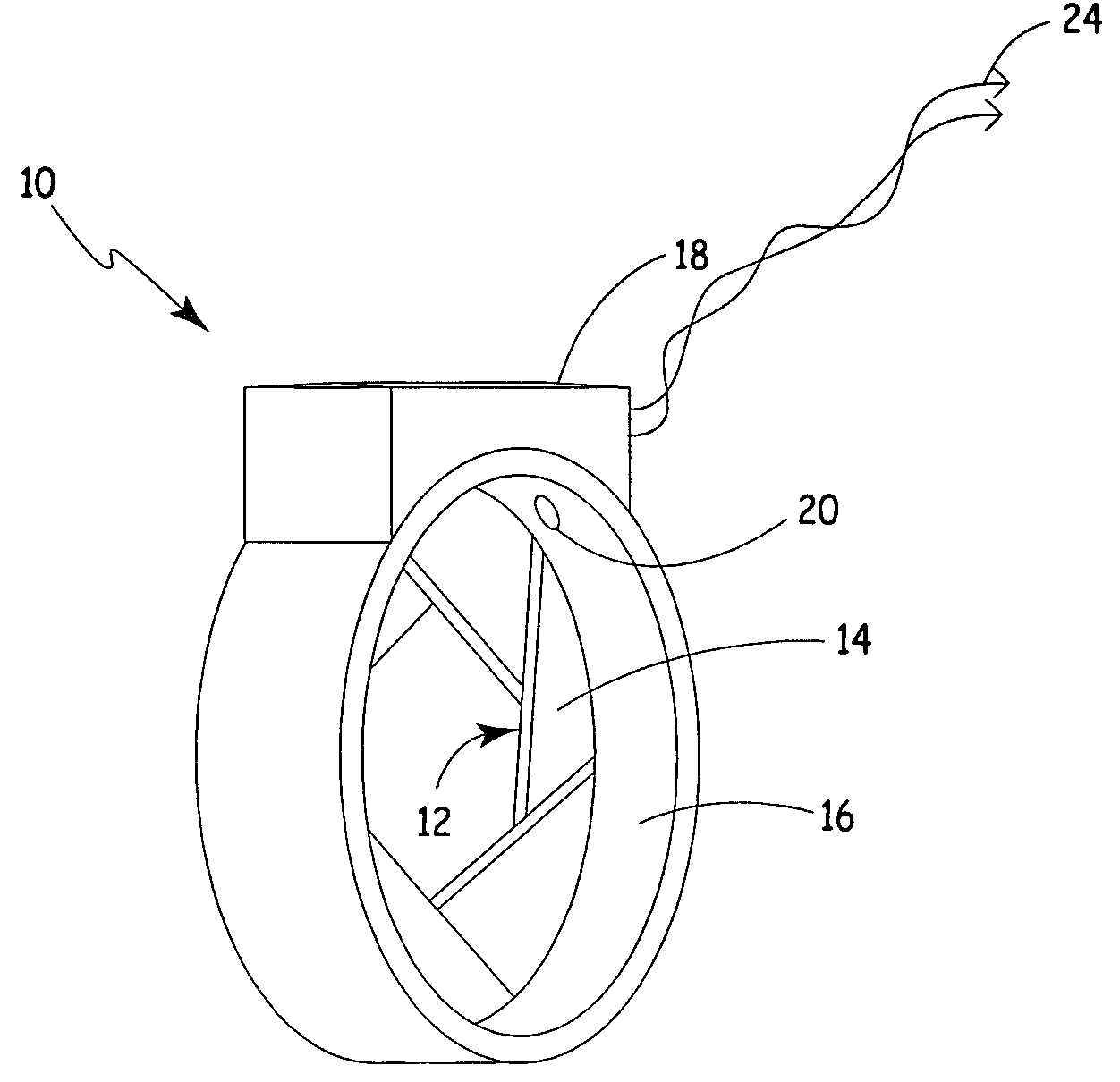
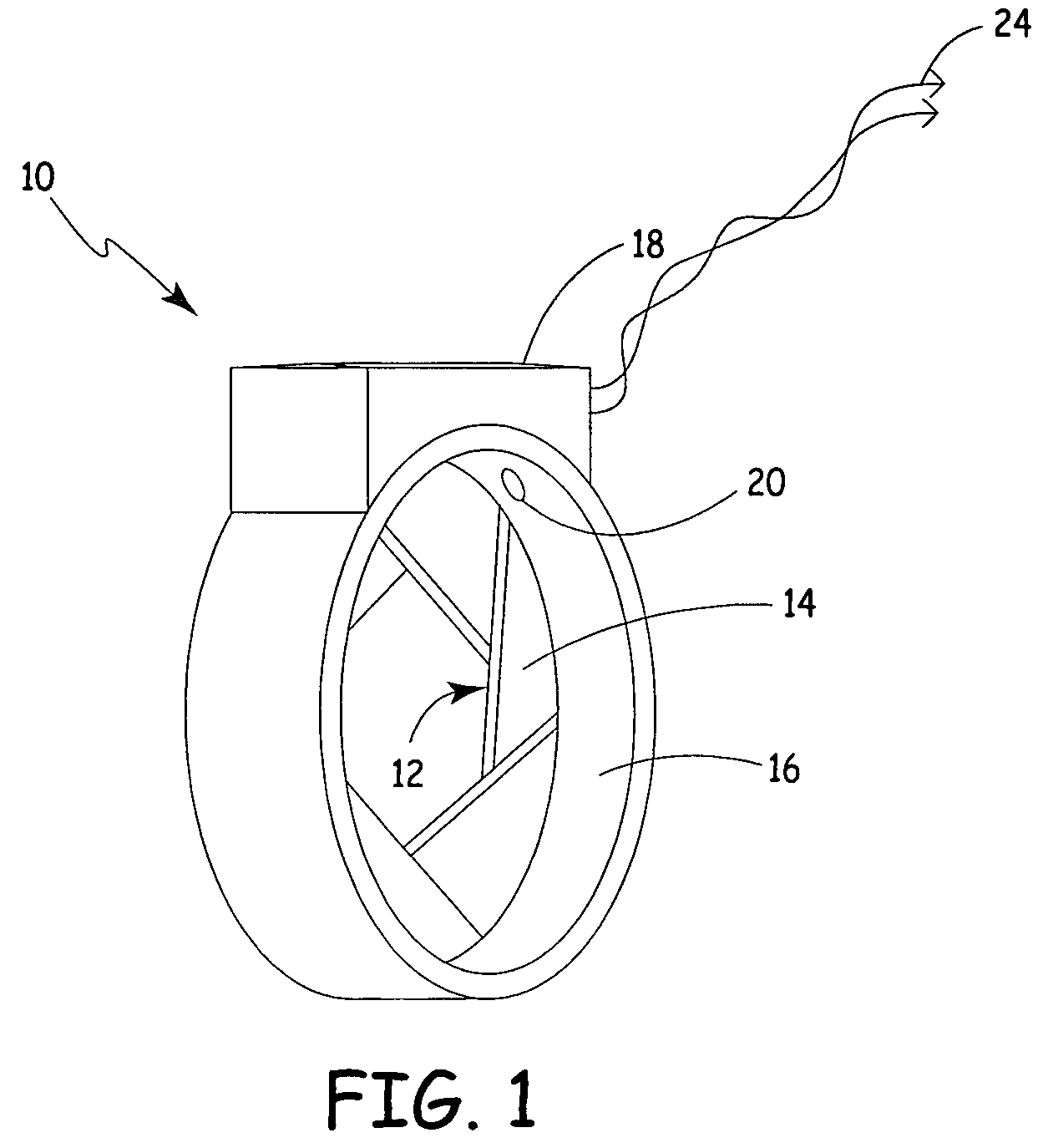
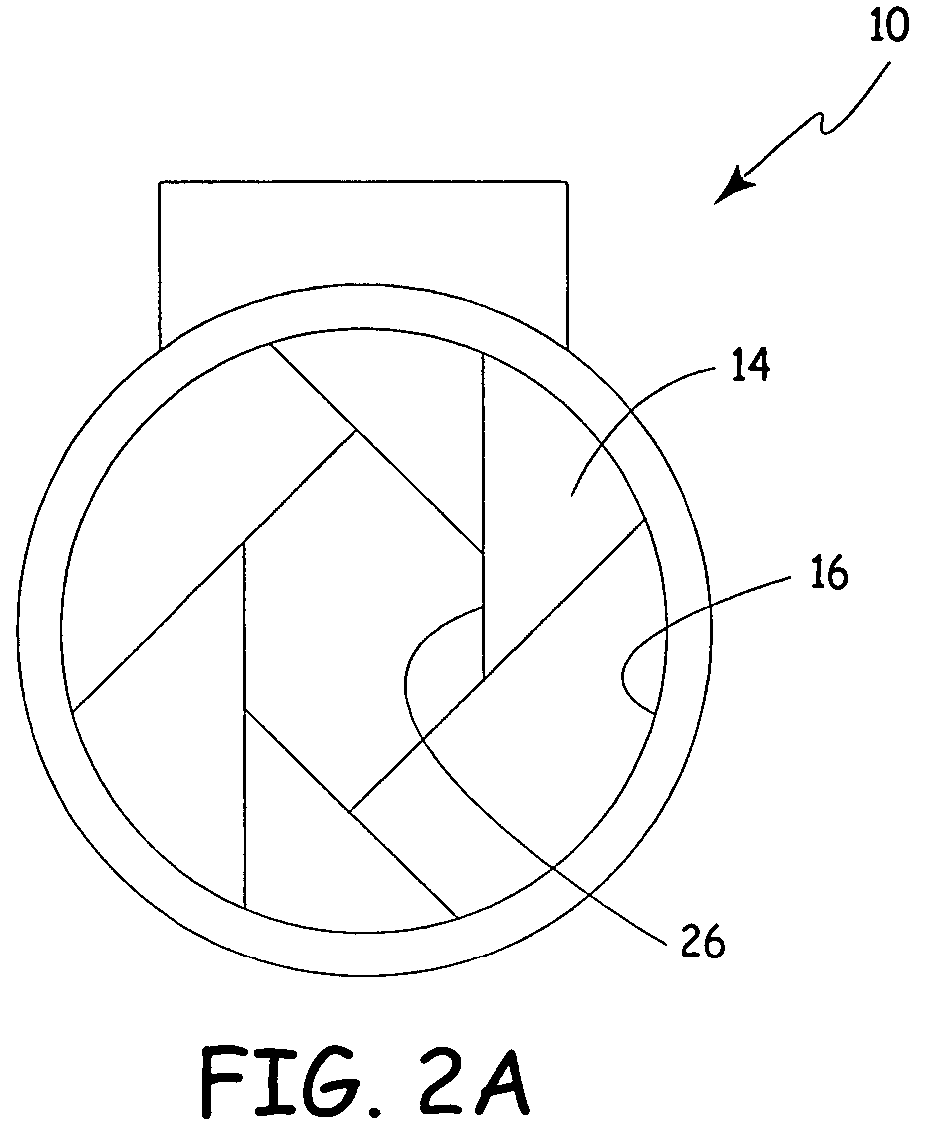
[0010]FIGS. 1 and 2A are perspective and front elevation views, respectively, of a process fluid flow device in accordance with embodiments of the present invention. Device 10 is a fully integrated process fluid flow control system in that it includes an actuator for changing fluid flow therethrough; a sensor for sensing fluid flow therethrough; and a controller for generating an actuator signal based upon the sensed flow signal and a control algorithm. In order to simplify fluid flow calculations, it is preferred that the fluid control mechanism be an iris-diaphragm flow valve. As the number of fingers used to create the iris is increased, the internal shape of the associated opening becomes more and more circular. Thus, once a sufficient number of fingers are used, for example six, the flow characteristics of the device begin to sufficiently approximate an orifice plate. Fluid flow through an orifice plate is well known and flow characteristics relative to orifice plates are well ...


PUM


Abstract

A process device providing total fluid flow control is provided. The device includes a closure mechanism disposed in a flow conduit. The closure mechanism, which is preferably an iris-type diaphragm, provides a variable internal diameter. The device includes a differential pressure sensor for sensing the differential pressure on opposite sides of the diaphragm. A controller receives an indication of differential pressure and generates a control signal to an actuator that actuates the closure mechanism. The closure mechanism, differential pressure sensor and controller create a closed-loop flow controller in a single process device.

Description

BACKGROUND OF THE INVENTION[0001]The present invention is related to industrial process control and measurement devices. More particularly, the present invention is related to an integrated device that controls fluid flow therethrough.[0002]Field devices, such as process variable transmitters, are used by a number of industries to remotely sense or control a process variable. Such variables are generally associated with fluids such as slurries, liquids, vapors, gasses, chemicals, pulp, petroleum, pharmaceuticals, food, and other fluid processing plants. Process variables may include pressure, temperature, flow, turbidity, density, concentration, chemical compensation, and other properties. Other examples of field devices include valves, actuators, heaters, and controllers.[0003]In the past, an industrial process fluid flow control system generally required multiple components. For example, a first field device, such as a process variable fluid flow transmitter would have a fluid obs...

Claims


Application Information

Patent Timeline
Patent Type & Authority Patents(United States)
IPC IPC(8): G01F1/42
CPCF16K3/03G05D7/0635
Inventor HEDTKE, ROBERT C.
Owner ROSEMOUNT INC
Learn More