Antenna apparatus utilizing minute loop antenna and radio communication apparatus using the same antenna apparatus
a technology of radio communication apparatus and minute loop antenna, applied in the field of antenna apparatus, can solve problems such as the decrease of antenna gain
- Summary
- Abstract
- Description
- Claims
- Application Information
AI Technical Summary
Benefits of technology
Problems solved by technology
Method used
Image
Examples
first preferred embodiment
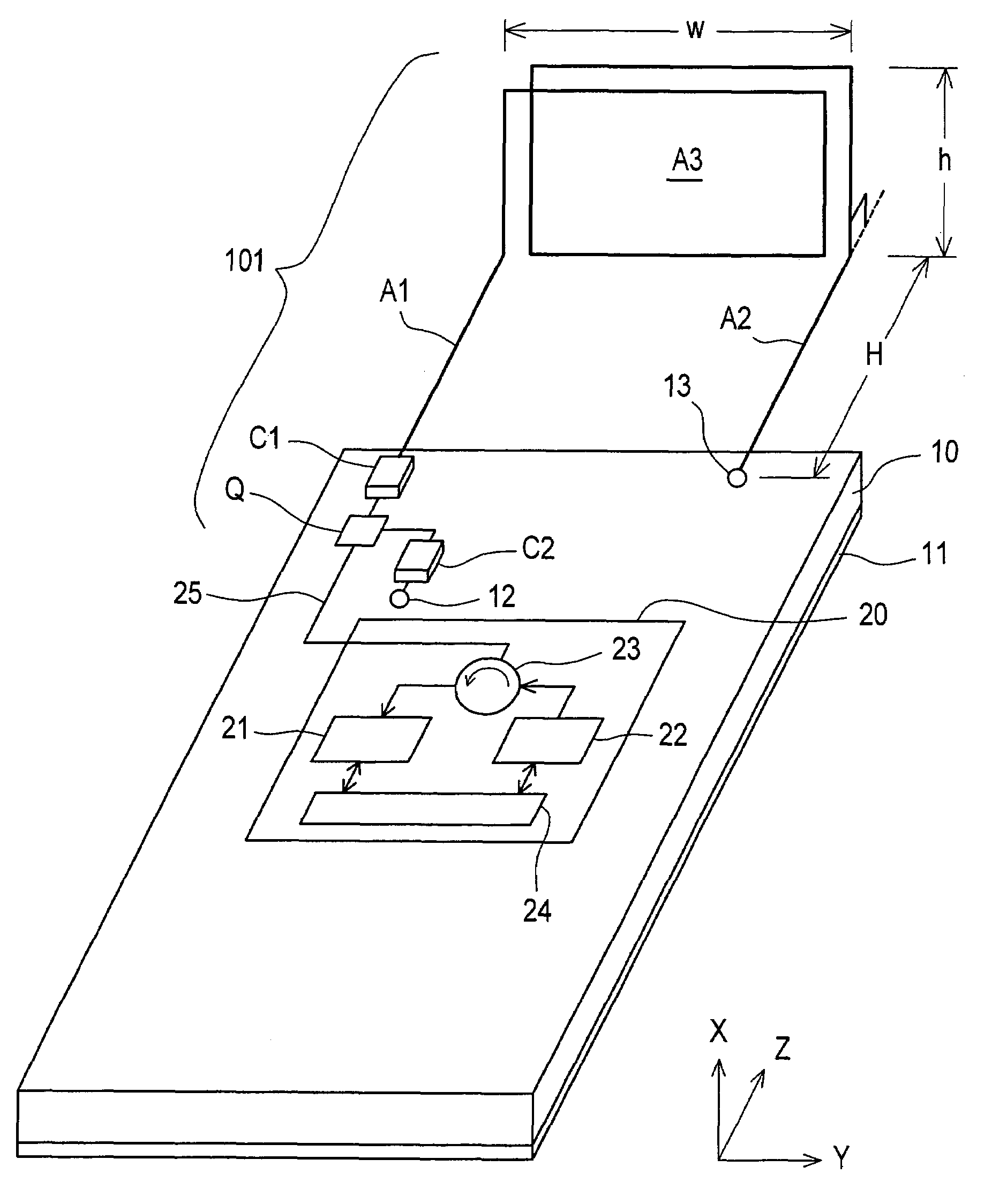
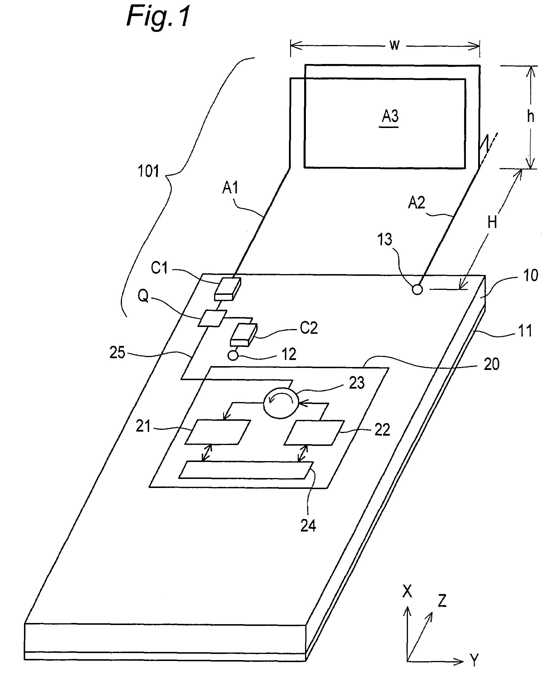
[0090]FIG. 1 is a perspective view showing a configuration of an antenna apparatus 101 according to a first preferred embodiment of the present invention. In FIG. 1, the antenna apparatus 101 according to the first preferred embodiment is characterized by including the following:
[0091](a) two antenna elements A1 and A2 which are substantially linear and arranged substantially in parallel to each other;
[0092](b) a rectangular minute loop antenna A3, which is connected to be inserted between these antenna elements A1 and A2, where the rectangular minute loop antenna A3 is provided in a direction perpendicular to the antenna elements A1 and A2, and has a number N of turns (N=1.5); and
[0093](c) a capacitor C1 which is connected to be inserted between the antenna element A1 and a feeding point Q.
[0094]Referring to FIG. 1, the feeding point Q is provided on an upper left edge portion of a dielectric substrate 10 which has a grounding conductor 11 formed on the whole rear surface in a long...
second preferred embodiment
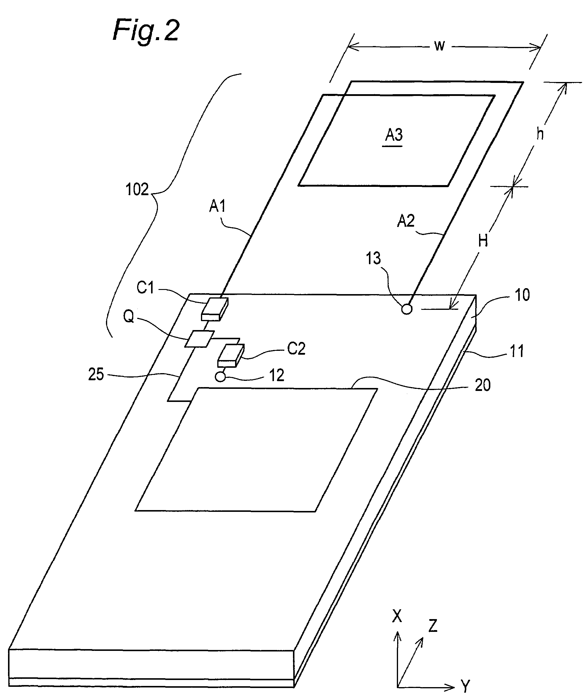
[0111]FIG. 2 is a perspective view showing a configuration of an antenna apparatus 102 according to a second preferred embodiment of the present invention. In FIG. 2, the antenna apparatus 102 according to the second preferred embodiment is characterized, as compared with the antenna apparatus 101 according to the first preferred embodiment, in that a loop axis direction of a minute loop antenna A3 is parallel to the X direction, that is, a loop surface of the minute loop antenna A3 is arranged substantially on the same plane as two antenna elements A1 and A2. In the antenna apparatus 102 as thus constituted, the loop axis direction of the minute loop antenna A3 is parallel to the X direction. In addition, the minute loop antenna A3 effectively operates as a current antenna and has an improved antenna gain for a vertically polarized wave when a metal plate 30 is located apart from the antenna apparatus 102 as described later in detail (See FIG. 14).
third preferred embodiment
[0112]FIG. 3 is a perspective view showing a configuration of an antenna apparatus 103 according to a third preferred embodiment of the present invention. The antenna apparatus 103 according to the third preferred embodiment is characterized, as compared with the antenna apparatus 101 according to the first preferred embodiment, in that a minute loop antenna A3 is arranged so that the loop axis direction of the minute loop antenna A3 is inclined by a predetermined inclination angle θ (03 and an antenna element A1 and that between the minute loop antenna A3 and an antenna element A2. The antenna apparatus 103 as thus constituted operates as a combination of the antenna apparatuses 101 and 102, and have a feature of the operation of the antenna apparatus 101 and that of the antenna apparatus 102. Accordingly, the antenna apparatus 103 can exhibit a directivity characteristic which compensates for disadvantages of the antenna apparatuses 101 and 102, and has an improved integrated ante...
PUM
 Abstract
Description
Claims
Application Information
 - R&D
- Intellectual Property
- Life Sciences
- Materials
- Tech Scout
- Unparalleled Data Quality
- Higher Quality Content
- 60% Fewer Hallucinations
Browse by: Latest US Patents, China's latest patents, Technical Efficacy Thesaurus, Application Domain, Technology Topic, Popular Technical Reports.
© 2025 PatSnap. All rights reserved.Legal|Privacy policy|Modern Slavery Act Transparency Statement|Sitemap|About US| Contact US: help@patsnap.com


