
Thrombus suction catheter with improved suction and crossing

a technology of thrombosis and suction catheter, which is applied in the field of thrombosis suction catheter, can solve the problems of limiting the ability of a check valve and a negative pressure maintenance mechanism to operate, oxygen and nutrients not being supplied to the heart itself, and affecting the operation of the patient's recovery

Active Publication Date: 2007-07-31
NIPRO CORP
View PDF13 Cites 93 Cited by
  • Summary
  • Abstract
  • Description
  • Claims
  • Application Information

AI Technical Summary

Benefits of technology

The present invention is a thrombus suction catheter with improved suction and crossing. It has a small pressure loss, a distal end opening with an angled cut surface, and a reinforcing wire. The catheter can be combined with a suction pump to create a continuous suction. The technical effects of this invention include improved blood clot removal, reduced pressure loss, and improved suction coverage.

Problems solved by technology

As a result, oxygen and nutrients are not supplied to the heart itself, whereby the function of the heart is lost.
If the thrombus thus formed is not removed early for reperfusion, death can result.
With the vacuum pump, there is a limit to the ability of a pump and a negative pressure maintenance mechanism using a check valve.
However, if the wall thickness is increased so as to avoid crushing, flexibility of the catheter is impaired.
Therefore, in the case where a lesion portion is at a position that is sharply curved (e.g., #3, #4 of the coronary arteries), crossing of the catheter is unsatisfactory, making it impossible to allow the catheter to reach the lesion portion.
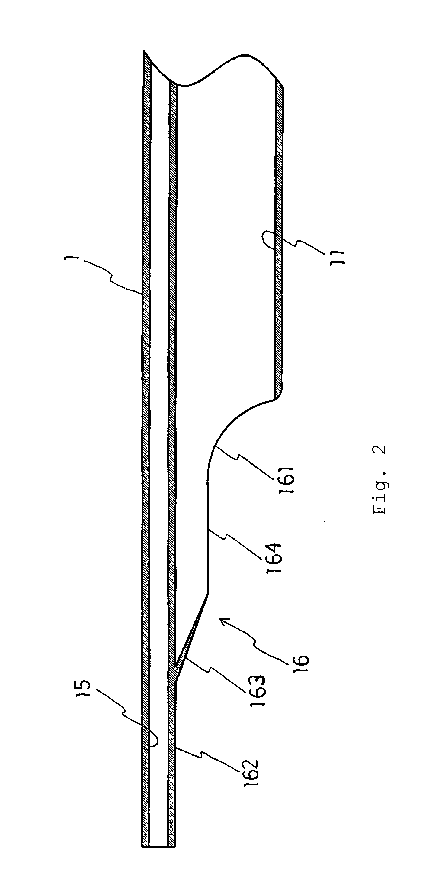
However, in the case where the vascular endothelium is expanded in a dome shape due to lipid core as described above, when the distal end of the catheter is cut straight, the surface of a lesion portion cannot be completely covered even if a cut surface is angled with respect to the longitudinal axis of the catheter.
As a result, the blood flows into the catheter from the distal end of the catheter during suction, and the negative pressure produced by a suction tool cannot be completely transmitted to the lesion portion, i.e., a thrombus or the vascular endothelium of the lesion portion.
Thus, sufficient suction cannot be obtained.

Method used


Image

  • Thrombus suction catheter with improved suction and crossing
  • Thrombus suction catheter with improved suction and crossing
  • Thrombus suction catheter with improved suction and crossing

Examples


Embodiment Construction

[0025]Next, the present invention will be described by way of examples with reference to the drawings.

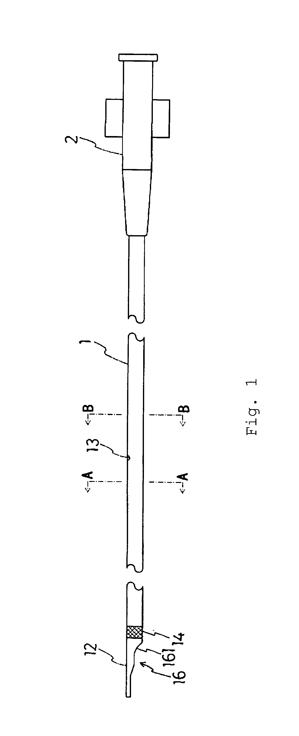
[0026]As illustrated in FIGS. 1 and 12, a thrombus suction catheter of the present invention is a tube having a distal end opening 12 formed by an angled cut surface. In the distal end opening 12, at least a part 161 on the proximal end side of the cut surface 16 is formed in a concave shape in the angled direction, and the distal end side 163, 164 of the cut surface 16 is formed to be flat and flexible and to neck down at its tip 162. With this distal end configuration, suction and crossing are significantly improved.

[0027]As shown in FIGS. 1, 4, 5 and 12, a preferred embodiment of the thrombus suction catheter includes a catheter body 1, a connector 2 provided at a proximal end of the catheter body 1, and a reinforcement wire 3 embedded in a reinforcement wire lumen 17 of the catheter body 1. The catheter body 1 is a tube formed of a flexible plastic such as polyamide elastomer, p...


PUM


Abstract

A thrombus suction catheter which is a tube having a distal end opening formed by an angled cut surface. In the distal end opening, at least a part on the proximal end side of the cut surface is formed in a concave shape in an angled direction, and the distal end side of the cut surface is formed to be flat and flexible. With the distal end configuration, suction and crossing are significantly improved.

Description

FIELD OF THE INVENTION[0001]The present invention relates to a thrombus suction catheter for removing a thrombus from coronary arteries, which is capable of removing atheroma by suction and has remarkably improved suction and crossing (reaching ability and smooth passage to a subject site).BACKGROUND OF THE INVENTION[0002]Acute myocardial infarction is a disease in which the blood vessel (coronary artery) for supplying oxygen and nutrients to the heart itself is clogged with a formed thrombus, and blood flow is blocked decreasing the function of the heart. About 40,000 people per year receive treatment for this disease in Japan. Heart disease is the first leading cause of death in Europe and the United States, and is the second leading cause of death following malignant neoplasma (cancer) in Japan, and is on the rise recently due to factors such as westernization of dietary culture and an increase in stress in social life. In recent years, treatment involving reopening of a clogged ...

Claims


Application Information

Patent Timeline
Patent Type & Authority Patents(United States)
IPC IPC(8): A61M25/00A61B17/22A61B19/00A61M1/00
CPCA61B17/22A61B17/3207A61M25/0068A61M25/008A61B19/54A61B2017/22039A61B2217/005A61M1/008A61M25/0029A61M25/0032A61B90/39A61M1/84
Inventor KATAISHI, YUICHIMORI, SATORUSANO, YOSHIHIKOKIKUCHI, TOSHIHIROISSHIKI, TAKAAKI
Owner NIPRO CORP
Learn More