Device for blow-molding or blow-drawing of thermoplastic containers

Inactive Publication Date: 2007-07-31
SIDEL PARTICIPATIONS SAS
View PDF7 Cites 10 Cited by
  • Summary
  • Abstract
  • Description
  • Claims
  • Application Information

AI Technical Summary

Benefits of technology

[0023]The aim of the invention is therefore to propose an improved structure of the molding devices which would make it possible to substantially increase the operating speed of the latter and which, as much as possible, would be simpler and less costly (in construction and maintenance) than the current machines.
[0025]In an embodiment that is preferred due to its simplicity, the compensating means comprise at least one spring interposed between said articulation and a frame supporting the mold. In addition, it is advantageous that the fixed end of the spring presses against a piece that can be moved to adjust the prestress of the spring.
[0026]Thanks to the use of compensating means as explained hereinabove, the effect of the inertia forces is notably compensated, in particular by attenuating the variation of amplitude of their resultant and above all by making the direction of this resultant invariant. In other words, the follower remains permanently in contact with the guidance cam, irrespective of the direction of movement of operation for the shaft 7; in addition the clearances have to be made up in only one direction, always the same.
[0027]As a result, it is possible to reproduce precisely the movement of the required operation, and to prevent the impacts and vibrations mentioned hereinabove for current machines.
[0029]Dispensing with the aforementioned elements makes it possible to free up space in the central portion of the molding device, which is otherwise extremely congested.
[0031]In total, the improved solution according to the invention makes it possible to significantly increase the production rate of the molding devices, and therefore of the whole container production plant, to reduce the cost of the machines and improve the operating dynamic of the machines thanks to the elimination of the impacts on the operating cam.

Problems solved by technology

In the configuration with two facing guidance cams envisaged hereinabove, it is not possible to use a single follower which would have to change in a very short time from bearing on one cam to the other with correlative inversion of its direction of rotation.
Such an arrangement complicates the device and increases its cost.
To prevent these impacts and vibrations causing a defective operation of the machine and / or damaging the machine, it is necessary to limit the speed of the latter and therefore to limit the rate of production.
There is currently a pressing requirement, from the users of the machines for producing containers, and in particular bottles, made of thermoplastic by blow-molding or blow-drawing, for a considerable increase in production rates, which involves in particular a considerable increase in the operating speed of the molding devices, an increase in speed which the current devices are not capable of supporting for the reasons explained hereinabove.

Method used


Image

  • Device for blow-molding or blow-drawing of thermoplastic containers
  • Device for blow-molding or blow-drawing of thermoplastic containers
  • Device for blow-molding or blow-drawing of thermoplastic containers

Examples


Embodiment Construction

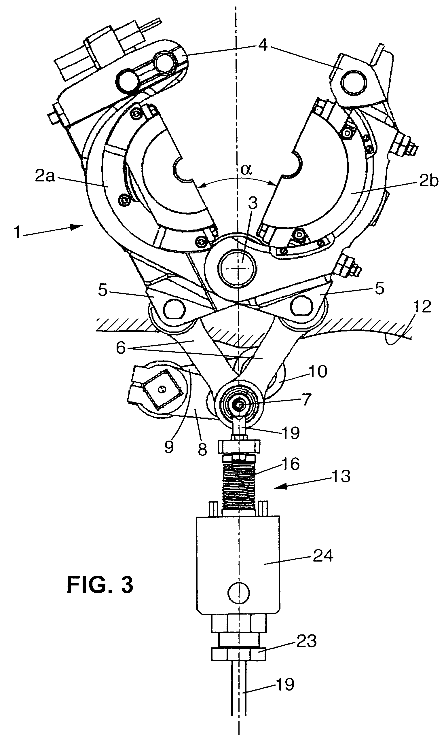
[0039]With reference first to FIG. 3, the mold 1 is shown in the same situation as in FIG. 1 and the same reference numbers have been retained to indicate the same members.

[0040]According to the invention, the articulation 7 common to the two link rods 6 is associated with compensating means 13 capable of acting in such a manner that the cam follower 10 is permanently kept in contact with the cam.

[0041]In the embodiment illustrated in FIG. 3, the arrangement is provided so that the follower 10 is kept in contact with the outer cam 12, that is to say against the cam whose surface is facing the center of rotation O. It will be noted that, in this case, the centrifugal forces act in a direction tending to press the follower 10 against the cam 12 which, via the compensating means 13, makes it easier to keep the follower permanently against the cam.

[0042]FIG. 4 gives an overview of the mold 1, in side view in perspective, this view revealing the bracket 14 supporting the mold on the rota...


PUM


Abstract

A device for blow molding or blow drawing of containers made of thermoplastic performs. The molding device is movable, mainly rotatable and includes at least one wallet-type mold provided with two mold-halves rotatable with respect to each other around an axis; two links which are connected to each other by one of the extremities thereof with the aid of a first pivot pin and pivotally connected to two mold-halves by the other extremities thereof on both sides of the common pivoting axis thereof; actuation devices which are connected to the first pivot pin and provided with at least one cam follower interacting with at least one respective fixed cam so that the first pivot pin is moved in a direction toward the mold or away therefrom, thereby opening or closing the mold. A compensating device acts so that at least one cam follower permanently contacts the respective cam.

Description

FIELD OF THE INVENTION[0001]The present invention concerns improvements made to the devices for blow-molding or blow-drawing of containers, such as bottles, flasks, etc. made from thermoplastic preforms, this molding device being movable, mainly rotatable, and comprising:[0002]at least one mold of the wallet type having two half-molds connected to one another by a mutual pivot shaft,[0003]two link rods secured to one another, by a first articulation, at one of their ends and secured with articulation, at their other end, respectively to the two half-molds either side of said mutual pivot shaft,[0004]and actuation means that are connected to said first articulation and that comprise at least one cam follower suitable for interacting with at least one respective fixed cam in order to generate an approximately linear movement of said articulation toward the mold or away from the latter, being accompanied respectively by the closure or the opening of the mold.DESCRIPTION OF THE PRIOR AR...

Claims


Application Information

Patent Timeline
IPC IPC(8): B29C49/56B29C49/06B29C49/36B29C49/42
CPCB29C49/56B29C49/06B29C49/42B29C49/36B29C2049/5664B29C2949/0715
Inventor ARAKELYAN, VIGENROUSSEAU, NICOLAS MARC ALEXANDREBRACHET, VINCENTLANGLOIS, PIERRE-FRANCOIS
Owner SIDEL PARTICIPATIONS SAS
Why Eureka
Try Eureka