
Self-contained flush-mount bulkhead air conditioning unit with novel evaporator/blower assembly housing

a technology of evaporator/blower assembly and air conditioning unit, which is applied in the field of housing, can solve the problems of difficult to obtain effective air circulation through the large volume of internal space to be cooled, allowing the evaporator assembly to take up much less space than a prior ac unit, and passenger buses presented particular problems

Active Publication Date: 2007-07-24
TRANSAIR MFG CORP
View PDF26 Cites 23 Cited by
  • Summary
  • Abstract
  • Description
  • Claims
  • Application Information

AI Technical Summary

Benefits of technology

The solution provides a lightweight, leak-resistant, and easily serviceable evaporator assembly that fits within bus bulkheads, ensuring effective air circulation and preventing corrosion, while maintaining efficient drainage even when the vehicle is in motion.

Problems solved by technology

Passenger buses presented particular problems due to the relatively large cooling load produced by the large number of passengers and the extensive window areas.
Also, it is difficult to obtain effective air circulation through the large volume of internal space to be cooled.
However, the above listed patents do not disclose a self-contained AC unit which has an evaporator assembly separated and located distally from the compressor and condenser, allowing the evaporator assembly to take up much less space than a prior AC unit.
As a result, the prior systems require a considerable amount of space, making them unsuitable for installation within the front or rear bulkhead of a bus or similar vehicle.
Further, one of the problems associated with installing evaporator components inside a vehicle has always been condensation.
Constant exposure of the metal welds to the water causes corrosion and leakage into the interior of the bulkhead.
Furthermore, operation of the AC unit while the bus is in motion can cause drainage problems for standard conventional drain pans, as the water sloshes laterally with the movement of the bus.

Method used


Image

  • Self-contained flush-mount bulkhead air conditioning unit with novel evaporator/blower assembly housing
  • Self-contained flush-mount bulkhead air conditioning unit with novel evaporator/blower assembly housing
  • Self-contained flush-mount bulkhead air conditioning unit with novel evaporator/blower assembly housing

Examples


Embodiment Construction

[0070]Although only a few preferred embodiments of the present invention are explained in detail, it is to be understood that these embodiments are given by way of illustration only. It is not intended that the invention be limited in its scope to the specific details of construction and arrangement of components set forth in the following description or illustrated in the drawings. Also, in describing the preferred embodiments, specific terminology will be resorted to for the sake of clarity. It is to be understood that each specific term includes all technical equivalents which operate in a similar manner to accomplish a similar purpose.

[0071]The present invention is directed to a self-contained evaporator assembly, generally designated by the reference numeral 5 (see FIG. 8B), which includes a housing for an air conditioning system to be used within a bus or similar vehicle. The evaporator assembly includes a coil subassembly, generally designated by the reference numeral 66 (see...


PUM


Abstract

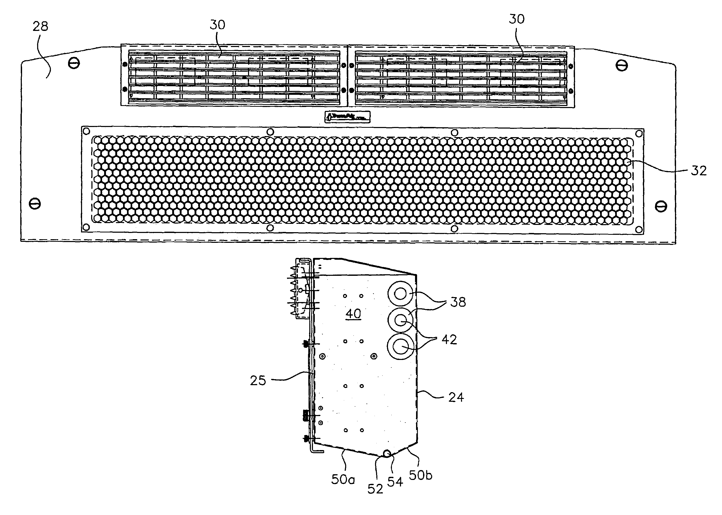
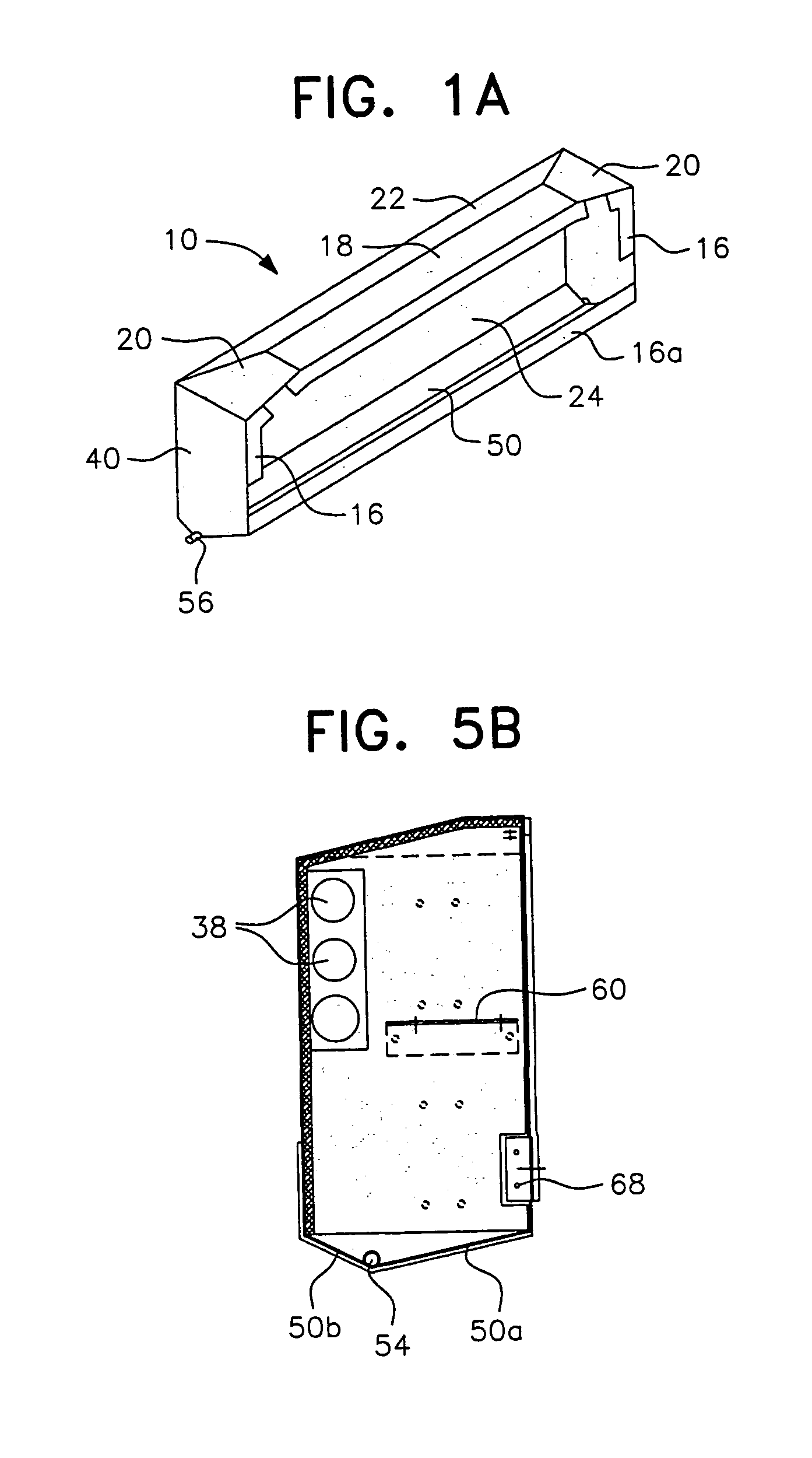
An air conditioning unit having a flush-mounted self-contained evaporator assembly adapted for mounting into the front or rear bulkhead of a bus or similar type vehicle. The evaporator assembly includes a specially designed housing to provide a compact self-contained unit that can fit in a small space, such as the bulkhead above a passenger compartment, while the associated compressor and condenser units are distally located. The housing has chamfered top surfaces so as to provide additional clearance within the bulkhead during installation, and a floor pan with two sloping surfaces forming an inverted apex. Lateral drains located at both ends of the apex facilitate drainage of condensate from the unit when the vehicle is in motion or in a non-level stationary position.

Description

[0001]This application is entitled to and hereby claims the priority of now abandoned U.S. Provisional application Ser. No. 60 / 528,867 filed Dec. 12, 2003.BACKGROUND OF THE INVENTION[0002]1. Field of the Invention[0003]This present invention generally relates to an air conditioning (AC) unit having an evaporator / blower housing adapted for mounting into the front or rear bulkhead of a bus or similar type vehicle for transporting a large number of occupants. More specifically, the invention relates to housings which are small, lightweight and easy to service and which allow evaporator / blower assemblies to be located distally from the compressor / condenser.[0004]2. Description of the Related Art[0005]Air conditioning units have been installed in various types of vehicles, with the design and operating parameters of the AC units adapted for installation in specific types of vehicles. Passenger buses presented particular problems due to the relatively large cooling load produced by the la...

Claims


Application Information

Patent Timeline
Patent Type & Authority Patents(United States)
IPC IPC(8): B60H1/32B60H1/00F25B5/00F25B39/02F25D17/06
CPCB60H1/00371B60H1/3229B60H2001/00242B60H1/3227
Inventor HAMMONDS, DAVID R.WHITESEL, DAVID E.
Owner TRANSAIR MFG CORP
Learn More