Spindle motor and method of manufacturing the same

a spindle motor and spindle technology, applied in the direction of magnetic circuit rotating parts, magnetic circuit shapes/forms/construction, instruments, etc., can solve the problem of difficult maintenance of open bearings, and achieve the effect of reducing the manufacturing cost of the spindle motor

Inactive Publication Date: 2007-07-24
MINEBEA CO LTD
View PDF22 Cites 5 Cited by
  • Summary
  • Abstract
  • Description
  • Claims
  • Application Information

AI Technical Summary

Benefits of technology

[0006]Thus, the present invention is made in light of the above problems and an object thereof is to reduce manufacturing cost as well as to provide a spindle motor less expensive and a method of manufacturing thereof.
[0008]The spindle motor thus constituted is less expensive than a spindle motor using ball bearings with shields.
[0010]By thus constructed, a spacer provided between a pair of ball bearings will not be required, so that the manufacturing cost of the spindle motor can be reduced.
[0012]By thus constructed, the manufacturing cost of the spindle motor can be reduced compared to a shaft rotatable spindle motor using ball bearings with shields.
[0014]By thus constructed, the manufacturing cost of the spindle motor can be reduced compared to a shaft fixed spindle motor using ball bearings with shields.
[0016]By thus constructed, the open ball bearings can be mounted on the spindle motor under a clean environment without foreign materials, etc. and the manufacturing cost of the spindle motor can be reduced compared to the spindle motor using the ball bearings with the shields.

Problems solved by technology

Moreover, open bearings are difficult to be maintained because foreign materials may enter the slide surfaces of the bearings before assembling the machine, resulting in numbers of difficulties when applying to the spindle motors 51 and 61.

Method used


Image

  • Spindle motor and method of manufacturing the same
  • Spindle motor and method of manufacturing the same
  • Spindle motor and method of manufacturing the same

Examples


first embodiment

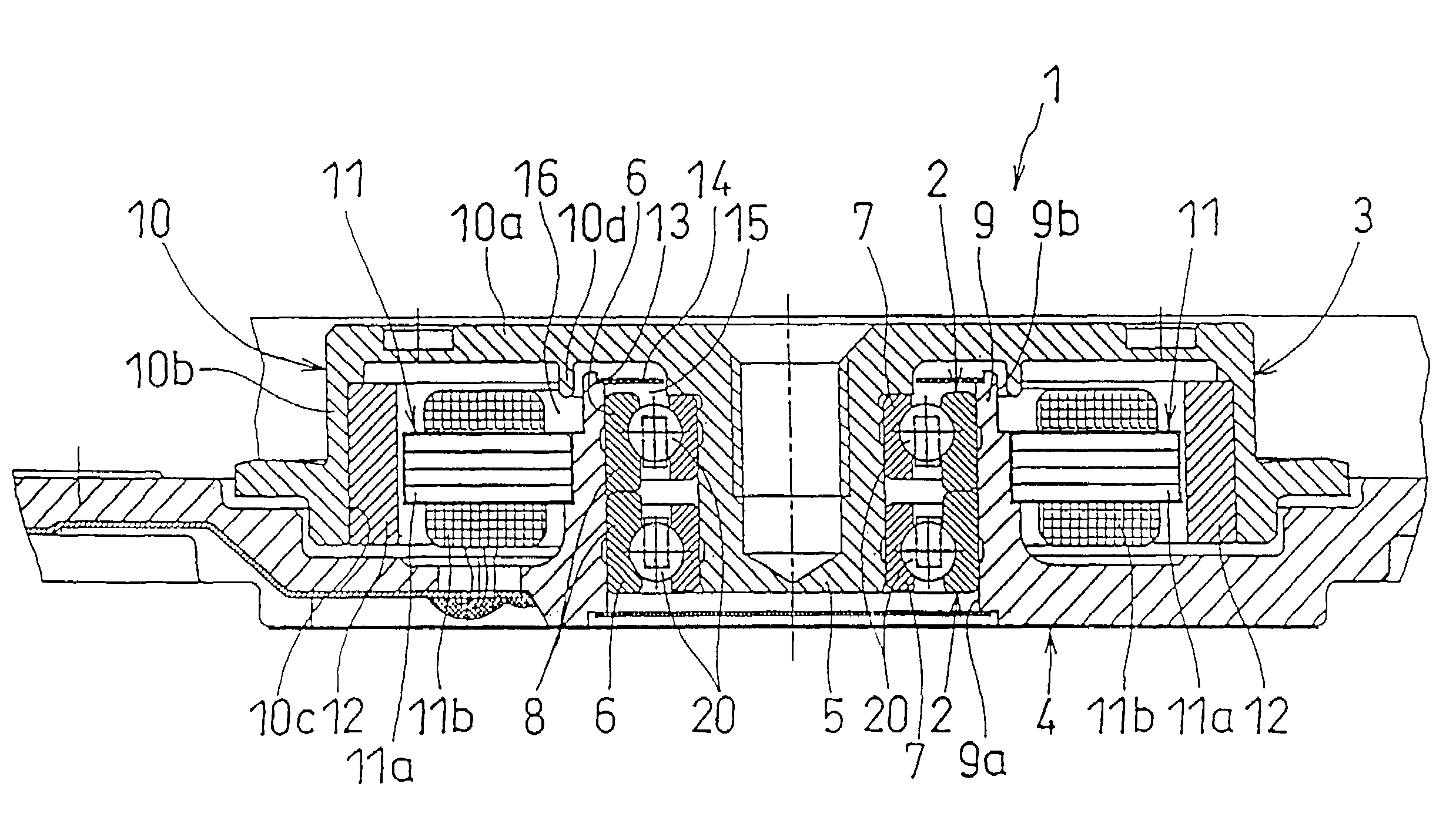
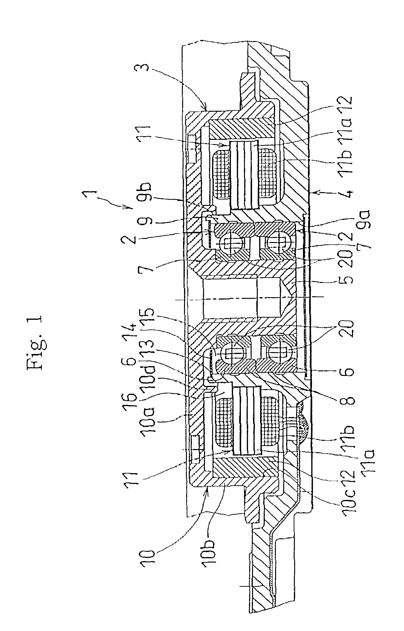
[0035]As described above, in the method of manufacturing the spindle motor 1 according to the present invention, the bearing washing process 17, the grease filling process 18 and the bearing mounting process 19 are sequentially performed in a clean room when assembling the spindle motor 1 whereby a pair of open bearings 2 can be mounted on the shaft rotatable spindle motor 1 with few contamination.

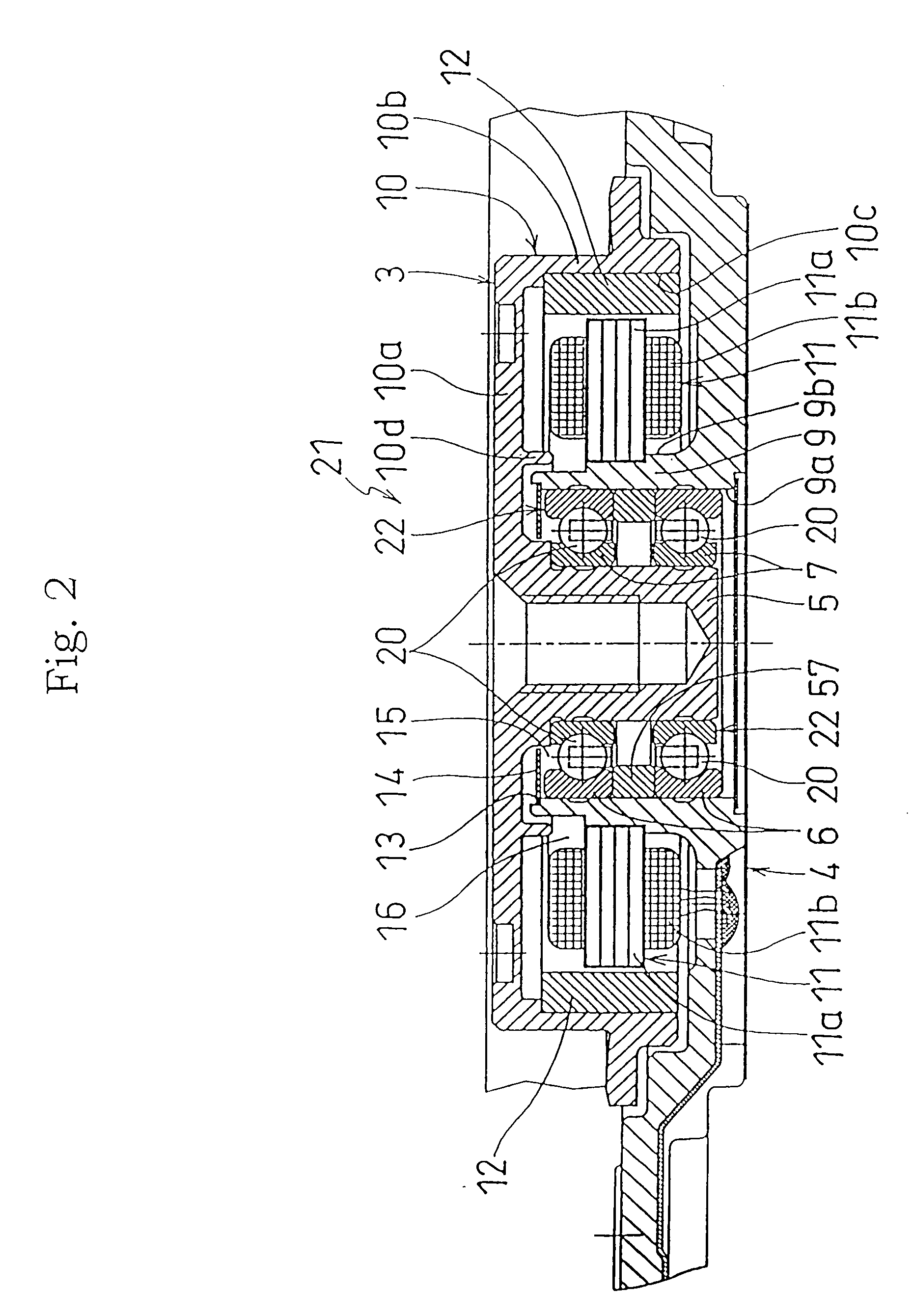
[0036]Noted that spacers 57 may be interposed between a pair of open bearings 2 as illustrated in FIG. 2 so as to form a shaft rotatable spindle motor 21 with general-purpose open bearings having no extending parts 8 in the outer rings 6.

[0037]Now, the spindle motor 1 according to the first embodiment of the present invention will be described in its function. In the spindle motor 1 of the present embodiment, the bearing washing process 17, the grease filling process 18 and the bearing mounting process 19 are sequentially performed when assembling the spindle motor 1 whereby a pair of open...

second embodiment

[0042]In a method of manufacturing the spindle motor 31 a pair of open bearings 2 can be mounted on the shaft fixed spindle motor 31 in the same manner as the above described shaft rotatable spindle motor 1 by sequentially performing the bearing washing process 17, the grease filling process 18 and the bearing mounting process 19 when assembling the spindle motor 31.

[0043]Noted that a spacer 57 may be interposed between a pair of open bearings 2 as illustrated in FIG. 4 so as to form a shaft fixed spindle motor 41 with general-purpose open bearings 22 having no extending parts 8 in the outer rings 6.

[0044]Now, the spindle motor 31 according to the second embodiment of the present invention will be described in its function. In the spindle motor 31 of the present embodiment, a bearing washing process 17, a grease filling process 18 and a bearing mounting process 19 are sequentially performed in the assembly process of the spindle motor 31. Therefore, a pair of open bearings 2 can be...


PUM

PropertyMeasurementUnit
inner diameteraaaaaaaaaa
outer diameteraaaaaaaaaa
diameteraaaaaaaaaa

Abstract

A spindle motor is formed so as to support a pivot of a rotor by a pair of open bearings.The open bearings thus constructed will be less expensive and simple structures, so that a manufacturing cost thereof is reduced compared to a conventional spindle motor using a pair of ball bearings with shields. Accordingly, a low-cost spindle motor can be provided.

Description

BACKGROUND OF THE INVENTION[0001]1. Field of the Invention[0002]The present invention relates to a spindle motor and a method of manufacturing thereof and more particularly to a spindle motor for supporting a rotor using open ball bearings and a method of manufacturing thereof.[0003]2. Description of the Related Art[0004]FIG. 5 shows one example of a spindle motor 51 for driving a hard disk drive device (hereinafter referred to as an HDD), more specifically, a shaft fixed spindle motor 51 wherein a shaft 55 is uprightly provided at the center of a base plate 54 and a rotor 53 is rotatably supported by interposing a pair of ball bearings 52 between the shaft 55 and the rotor 53. Further, FIG. 6 shows a shaft rotatable spindle motor 61 for an HDD wherein a substantially cylindrical fixed shaft 66 coaxial with a pivot 65 of a rotor 63 is uprightly provided and the rotor 63 is made to be rotatable by interposing a pair of ball bearings 52 between the fixed shaft 66 and the pivot 65 of t...

Claims


Application Information

Patent Timeline
Patent Type & Authority Patents(United States)
IPC IPC(8): F16C33/66B21D53/10B21K1/76B23P17/00B23P6/00F16C19/36F16C19/00F16C19/06F16C33/58F16C35/06H02K5/173H02K15/14H02K21/22
CPCF16C19/00F16C19/06F16C19/54F16C33/6622H02K5/1735H02K5/1737F16C35/061Y10T29/49702Y10T29/49009Y10T29/497F16C2235/00
Inventor OBARA, RIKUROFUKUNAGA, KENJI
Owner MINEBEA CO LTD
Why Eureka
Try Eureka