Eureka AIR delivers breakthrough ideas for toughest innovation challenges, trusted by R&D personnel around the world.

Personal authentication device

a technology of authentication device and user, applied in the field of personal authentication device, can solve the problems of difficult forgery, difficult to obtain repeatability patterns, and lack of pattern clearness in captured images, so as to prevent users from feeling pressur

Active Publication Date: 2007-07-17
HITACHI ASTEMO LTD
View PDF24 Cites 62 Cited by
  • Summary
  • Abstract
  • Description
  • Claims
  • Application Information

AI Technical Summary

Benefits of technology

[0010]An object of the present invention is to provide a compact authentication device that prevents the user from feeling pressure and that is strong against the external light, when capturing an image of a finger blood vessel pattern by using the transmitted light.
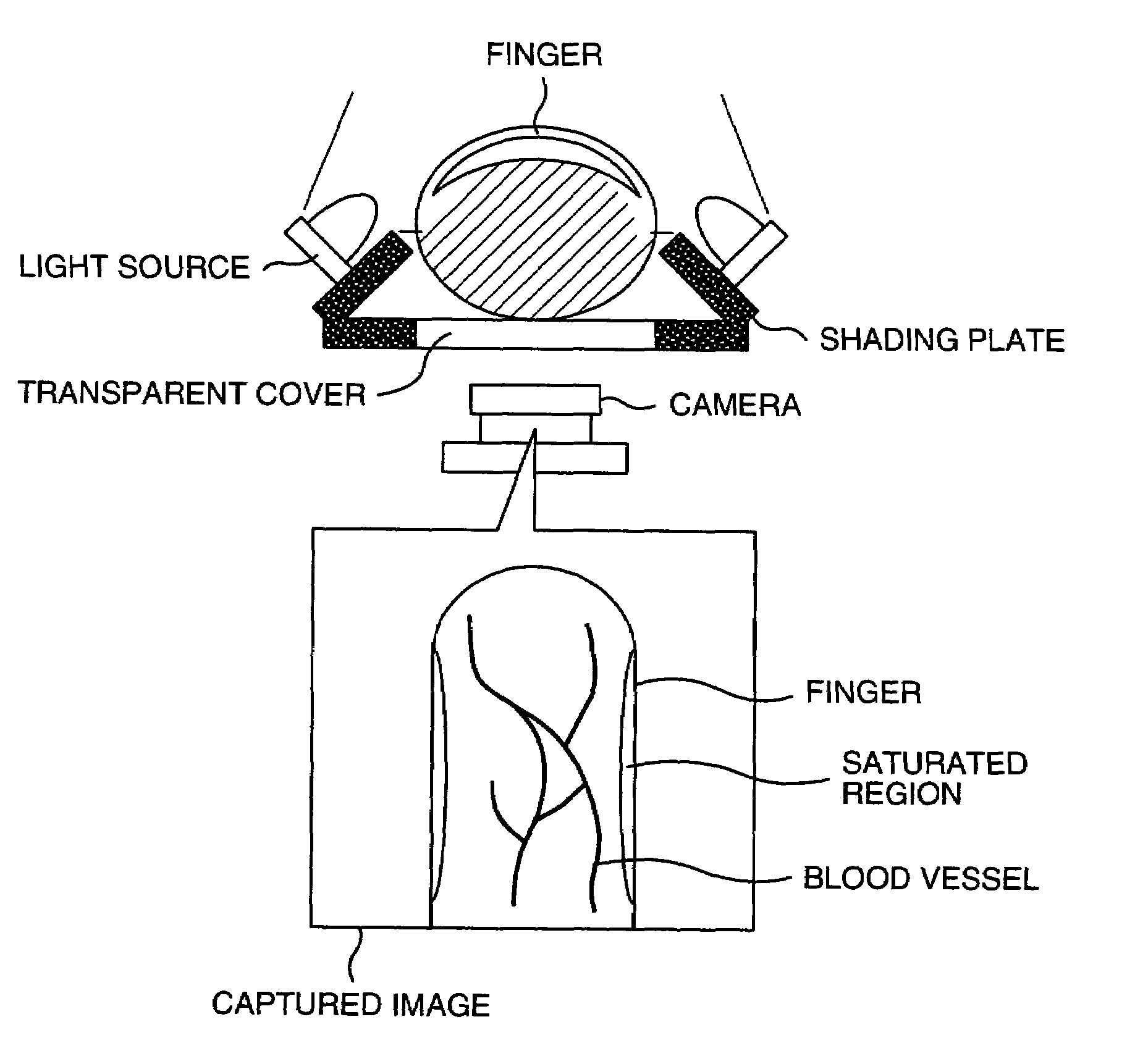
[0011]Another object of the present invention is to reduce the saturated regions in the pattern obtained by capturing an image of the finger, and thereby provide a clear finger blood vessel pattern, in the case where light sources are disposed in the finger side face direction.

Problems solved by technology

Furthermore, since the blood vessel pattern is not a living body surface, which can be easily absorbed, but is an internal feature, the authentication method using the blood vessel pattern has an advantage that forgery is difficult.
Therefore, the captured image lacks pattern clearness.
As a result, it is difficult to obtain a pattern having repeatability, unless the blood vessel is clear to such a degree that visual recognition is possible even under the visible light, like a vein located in back of a hand having thin epidermis.
This means that the pattern can be reproduced easily, and there is a serious problem as a security technique in the aspect of forgery resistance.
In addition, because of the property that reflection of light from the epidermis is intense, the influence of a change of the skin surface, such as an injury, skin chapping, or wrinkles, on the captured image is inevitably great.
On the other hand, in the transmission method, there is a limit in the thickness of a living body through which light can be transmitted.
Furthermore, if an operation button or the like is disposed in the finger tip position, the user might waver in grasping the button position.
However, there is a problem that the hand that can be used for authentication is limited to the left hand or the right hand according to the position relation between the light source and the camera. FIG. 10 shows the case where the light source is disposed on the right side.
In other words, in an authentication device having a camera part on the left side and a light source part on the right side, authentication other than that using the right hand is not practical.
However, there are many problems, such as a cost increase and necessity of camera switching.
For the same reason as that in the reflection method, it becomes difficult to obtain a blood vessel pattern from each of the palm side portions.
In that case, however, the light amount reaching the vicinity of the center on the palm surface of the finger conversely becomes insufficient, resulting in a problem that the blood vessel pattern cannot be obtained.
This becomes a cause of aggravation in the authentication performance under the strong external light, such as the setting sunlight.

Method used


Image

  • Personal authentication device
  • Personal authentication device
  • Personal authentication device

Examples


Embodiment Construction

[0033]Hereafter, an embodiment of the present invention will be described in detail.

[0034]Herein, a lower side of a finger means a surface of a palm side or an image capture part, and an upper side of a finger means a back side of a hand and a surface opposite to the surface of the image capture part. A side face of a finger means a surface of the finger other than the palm side and the back side of the finger, or a surface other than the upper side and the lower side.

[0035]Herein, transmitted light means light that is transmitted through the inside of a finger, and the term “transmitted light” is used in meaning as distinguished from light reflected by the surface of the skin or the epidermis.

[0036]The saturated regions in the sides of the finger as typically shown in FIG. 13 are caused by light emitted from the light source and reflected directly by the surface of the skin arriving at the camera. Unless the ratio of the reflected light to the transmitted light is adjusted suitably...


PUM


Abstract

A compact authentication device that prevents user from feeling pressure and is strong against external light, when capturing an image of a finger blood vessel pattern with transmitted light. The device includes a guidance part for determining the finger position, a light source disposed on at least one side of the guidance part to emit light to be transmitted though the finger, an image capture part for capturing the transmitted light, a shading unit for limiting an irradiation region of the light, a finger thickness measuring unit, a unit for controlling a light amount of the light source based on a result of the measurement, a unit for recording registered image patterns of the finger, a unit for collating a captured image pattern from the image capture part with the registered patterns, and a unit for controlling different processing according to the collation result.

Description

BACKGROUND OF THE INVENTION[0001]The present invention relates to a personal authentication device using a living body, and in particular a living body personal authentication device based on a blood vessel pattern of a finger.[0002]As a highly convenient security method that does not require to carry a key or the like and reduces the risk of illegal use due to loss or a theft, living body authentication using a part of a personal body, such as a fingerprint, iris, or a blood vessel pattern, as a key is attracting attention. Among them, an authentication method using a blood vessel pattern brings about little rejection symptom. Because the authentication method does not remind us of crime investigation unlike the fingerprint, and an eyeball is not directly exposed to light unlike the iris. Furthermore, since the blood vessel pattern is not a living body surface, which can be easily absorbed, but is an internal feature, the authentication method using the blood vessel pattern has an ...

Claims


Application Information

Patent Timeline
Patent Type & Authority Patents(United States)
IPC IPC(8): G06K9/00A61B5/117G06T1/00G06V40/145G06V40/14G07C9/00
CPCG06K9/00G06K9/00013G07C9/00158G06K2009/00932G07C9/37G06V40/14G06V40/145G06F18/00
Inventor NAGASAKA, AKIOMIYATAKE, TAKAFUMIMIURA, NAOTOKASHIMURA, YUICHI
Owner HITACHI ASTEMO LTD
Why Eureka
Eureka Blog
Learn More