Substrate treating apparatus
a technology of treating apparatus and substrate, which is applied in the direction of carburetating air, fuel gas production, cleaning using liquids, etc., can solve the problems of difficult to treat conventional equipment has difficulty in treating all the wafers w uniformly, so as to achieve the effect of increasing the
- Summary
- Abstract
- Description
- Claims
- Application Information
AI Technical Summary
Benefits of technology
Problems solved by technology
Method used
Image
Examples
first embodiment
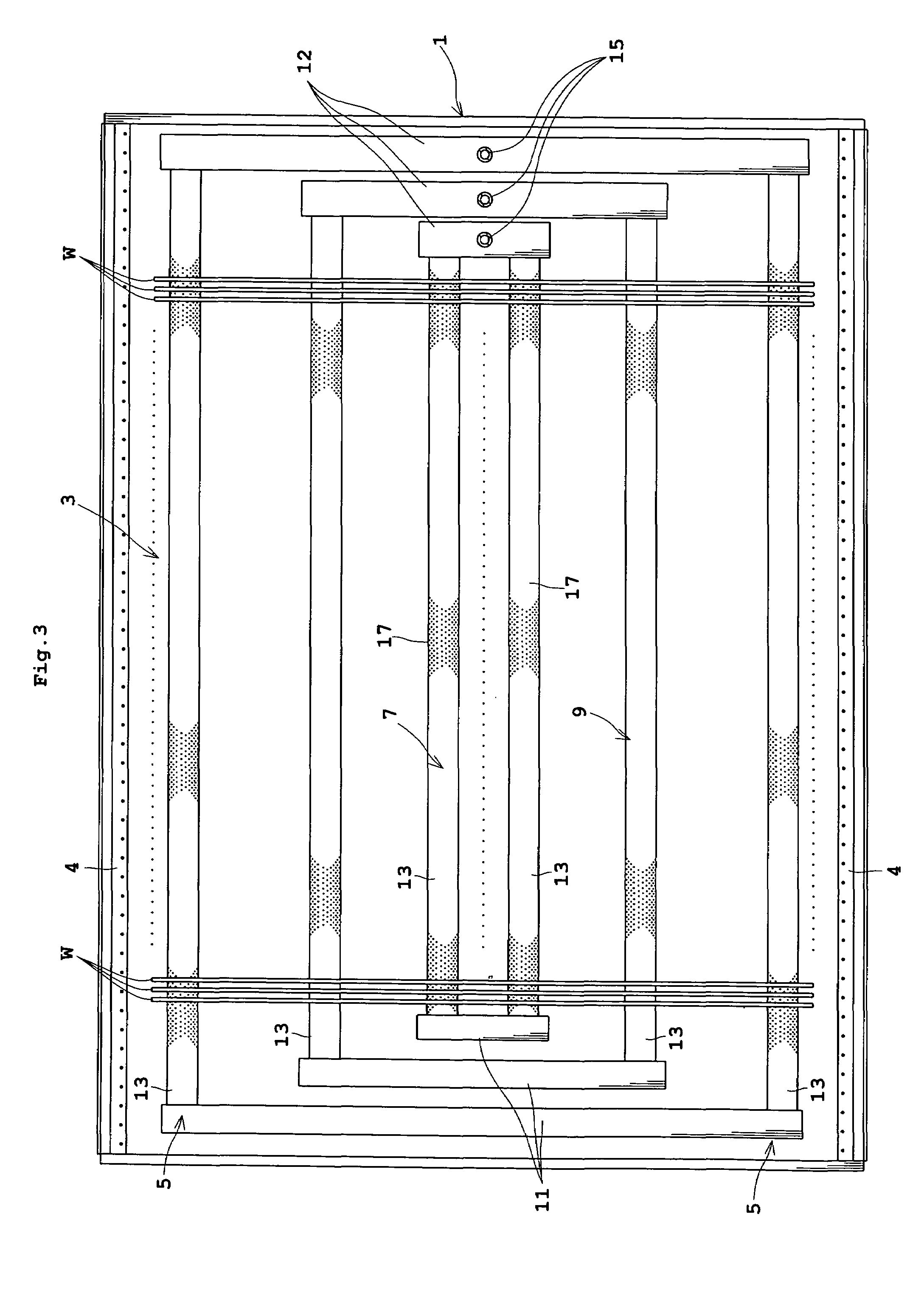
[0043]FIG. 3 is a plan view showing an outline of a substrate treating apparatus in a first embodiment. FIG. 4 is a side view showing the outline of the substrate treating apparatus in the first embodiment.
[0044]This substrate treating apparatus includes a treating tank 1 for storing a treating solution. The treating solution may be sulfuric acid, for example. The treating tank 1 has bubblers 3, which correspond to the bubble generating device, arranged adjacent the bottom thereof for supplying a gas. One example of the gas is ozone. The treating tank 1 has filling pipes 4 arranged adjacent the bottom thereof for supplying the treating solution, and a collecting tank (not shown) for collecting the treating solution overflowing the treating tank 1.
[0045]The bubblers 3 include a pair of opposite end bubblers 5, a pair of central bubblers 7 arranged in a central region in plan view between the opposite end bubblers 5, and a pair of auxiliary bubblers 9 arranged between the opposite end...
second embodiment
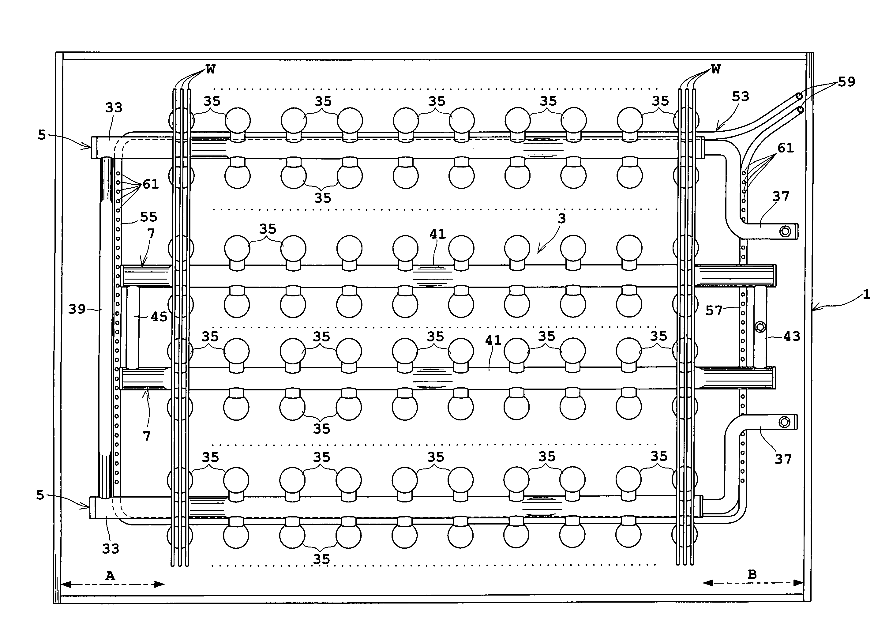
[0062]FIG. 8 is a plan view showing an outline of a substrate treating apparatus in a second embodiment. FIG. 9 is a side view showing the outline of the substrate treating apparatus in the second embodiment.
[0063]This substrate treating apparatus includes a treating tank 1 for storing a treating solution. The treating solution may be sulfuric acid (H2SO4), for example. The treating tank 1 has bubblers 3 arranged adjacent the bottom thereof for supplying a gas. One example of the gas is ozone. The treating tank 1 has filling pipes, not shown, arranged adjacent the bottom thereof for supplying the treating solution, and a collecting tank, not shown, for collecting the treating solution overflowing the treating tank 1.
[0064]The bubblers 3 include opposite end bubblers 5, and central bubblers 7 arranged between the opposite end bubblers 5. These bubblers 3 are formed of quartz glass which is resistant to the treating solution such as sulfuric acid. The opposite end bubblers 5 include m...
third embodiment
[0086]Next, a third embodiment of this invention will be described with reference to FIG. 12.
[0087]FIG. 12 is a side view showing an outline of a substrate treating apparatus in the third embodiment.
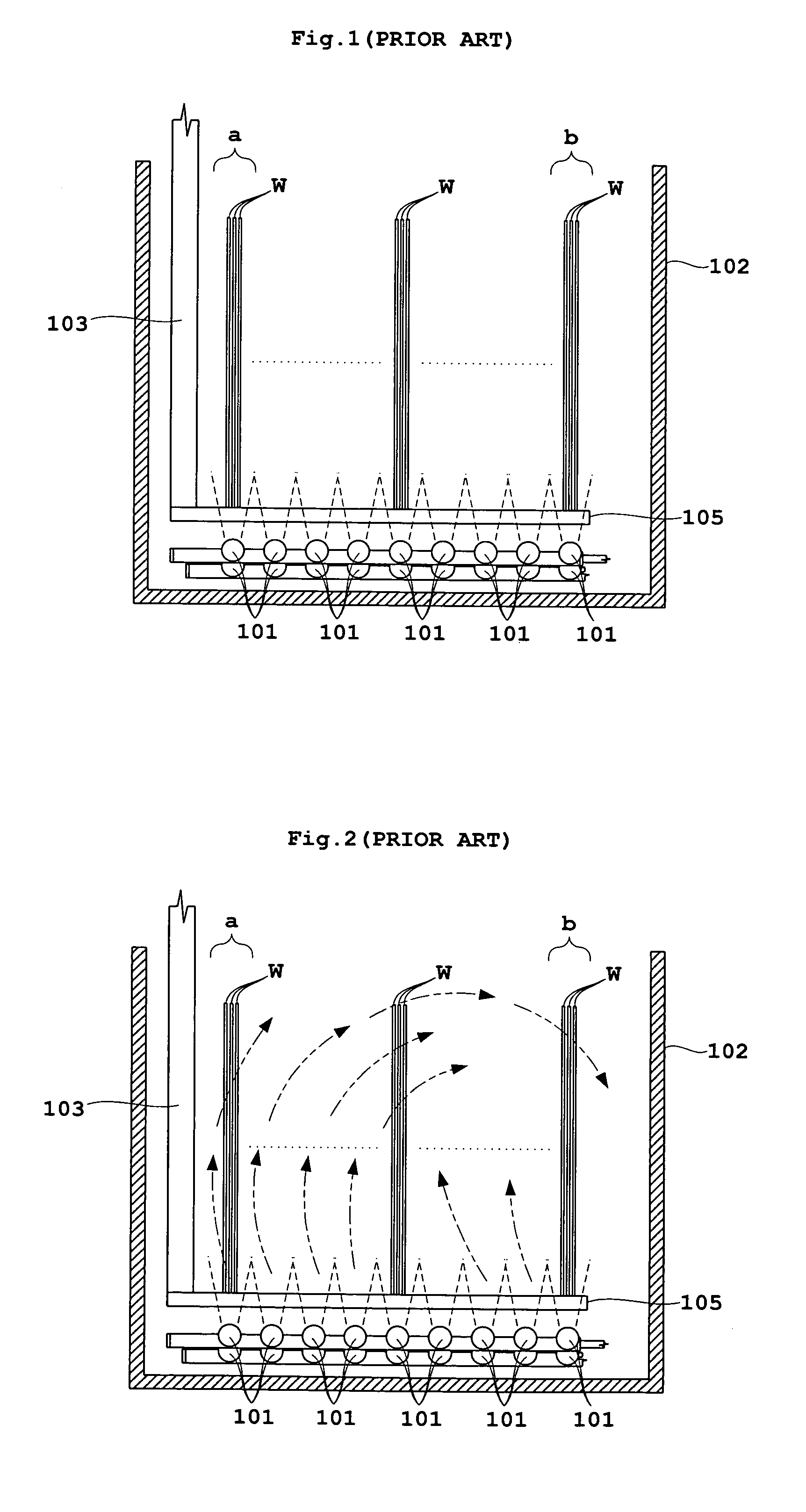
[0088]The second embodiment and its modifications described above have constructions for preventing vortices formed by the bubbles from the bubblers 3 by generating bubbles independently of the bubblers 3. As distinct from these constructions, the third embodiment positively form currents of the treating solution in order to prevent vortices produced in the treating tank 1 by the bubbles from the bubblers 3.
[0089]The treating tank 1 includes a first current generating nozzle 63 and a second current generating nozzle 65. The first current generating nozzle 63 is attached to the side wall of the treating tank 1 adjacent the space A, and has a discharge bore or bores 63a formed in an upper surface thereof for spouting the treating solution upward (two-dot chain lines in FIG. 12). The second...
PUM
| Property | Measurement | Unit |
|---|---|---|
| diameter | aaaaa | aaaaa |
| flow rate | aaaaa | aaaaa |
| resistance | aaaaa | aaaaa |
Abstract
Description
Claims
Application Information
 - R&D
- Intellectual Property
- Life Sciences
- Materials
- Tech Scout
- Unparalleled Data Quality
- Higher Quality Content
- 60% Fewer Hallucinations
Browse by: Latest US Patents, China's latest patents, Technical Efficacy Thesaurus, Application Domain, Technology Topic, Popular Technical Reports.
© 2025 PatSnap. All rights reserved.Legal|Privacy policy|Modern Slavery Act Transparency Statement|Sitemap|About US| Contact US: help@patsnap.com


