Eureka AIR delivers breakthrough ideas for toughest innovation challenges, trusted by R&D personnel around the world.

Laminate for printing and, printing method and printed matter using the same

a technology of laminate and printing method, applied in the field of printing laminate, can solve the problems of blurred edges, inability to obtain sufficient color density, and impair image sharpness, and achieve the effects of weak affinity, weak affinity, and permeability of dyes

Inactive Publication Date: 2007-07-03
KIWA CHEM IND CO LTD
View PDF48 Cites 20 Cited by
  • Summary
  • Abstract
  • Description
  • Claims
  • Application Information

AI Technical Summary

Benefits of technology

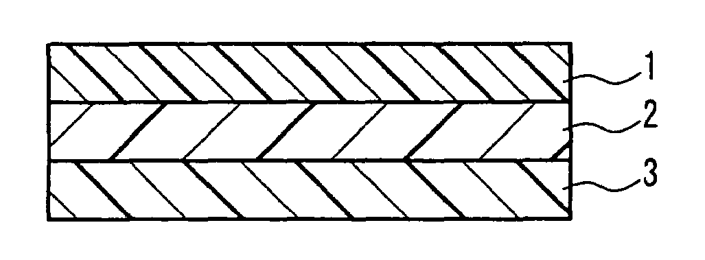
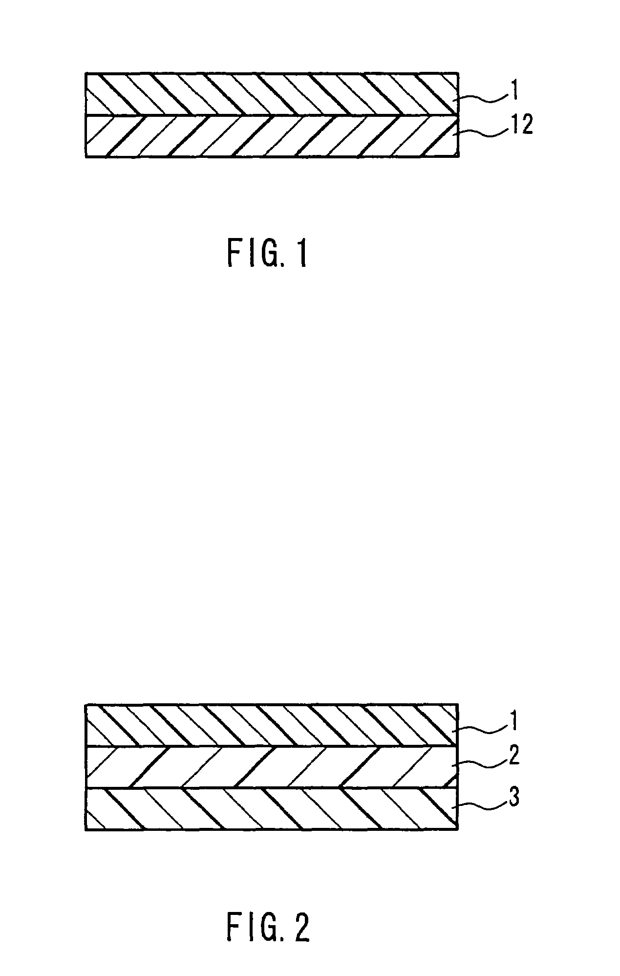
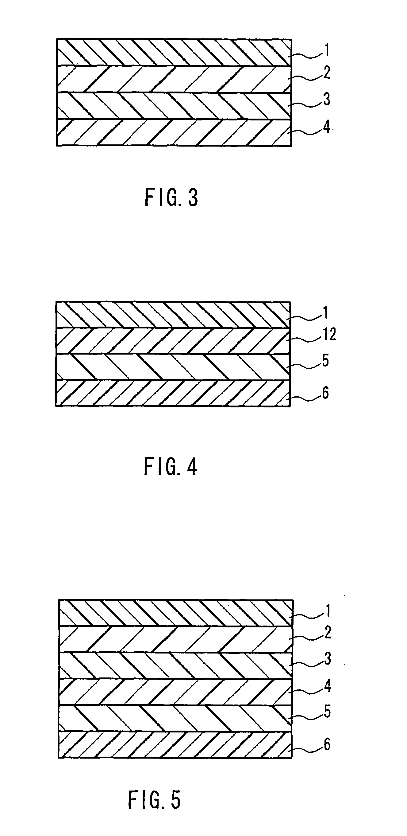
The present invention provides a printing laminate that can prevent the migration of a sublimable dye and to provide a printing method and a print using the printing laminate. The printing laminate includes a surface resin layer that has weak affinity with the sublimable dye and a dye migration preventive colorable resin layer that has affinity with the dye and prevents migration of the dye. The printing method involves conducting printing with respect to a transfer paper using an ink containing a sublimable dye and bringing the image formation face of the transfer paper in contact with the surface resin layer, followed by a heat treatment so as to sublimate the sublimable dye, allowing diffusion of the dye into the dye migration preventive colorable layer or a colorable resin layer to dye the same. The print produced using this printing laminate and method has improved quality and durability.

Problems solved by technology

In this step, however, if the transfer temperature and the transfer time are lower and shorter than the optimum conditions for the transfer printing, sufficient density of the colors cannot be obtained.
Alternatively, if they are in excess of the optimum conditions, problems occur in which the sublimable dye extends to penetrate and migrate into a layer continuous with the colorable resin layer, such as a glue layer and an adhesive layer that are provided for the attachment to a substrate, which impairs the sharpness of the image or makes the edge of the image blurred.
This means the diffusion of the dye that is to be kept within the colorable resin layer, which causes the problems of discoloration, the blurred edge of an image and the like.
However, the technology of JP 2002-79751 A has the problem that, when a polyester film used is not stretched, the migration of a dye cannot be prevented.
However, such a film also is insufficient for keeping the sharpness of an image for a long time within the colorable layer, and the edge of the printed image becomes blurred in a short time.
Furthermore, when a biaxially stretched polyester film is adopted as a substrate used in the course of the manufacturing process, the biaxially stretched polyester film contracts due to the heat applied during the sublimation dyeing, which causes a problem that wrinkles and streaks occur in the printing laminate.
In addition, in the case where the biaxially stretched polyester film is to be attached on a three-dimensionally curved surface, for example, for wrapping vehicles, it becomes difficult to attach the film on the curved surface because the film lacks flexibility, elongation percentage and the like because of its stiffness.

Method used


Image

  • Laminate for printing and, printing method and printed matter using the same
  • Laminate for printing and, printing method and printed matter using the same
  • Laminate for printing and, printing method and printed matter using the same

Examples


reference example 1

[0072]1000 parts of n-butyl acetate was put in a four-necked flask equipped with a stirrer, a thermometer, an inner gas inlet and a condenser, and a temperature was increased to 100° C. Next, a mixture including: 650 parts of methyl methacrylate; 245 parts of n-butyl methacrylate; 100 parts of 2-hydroxy ethyl methacrylate; 5 parts of methacrylic acid; and 15 parts of t-butyl peroxy-2-ethyl hexanoate was dropped at 110° C. over 4 hours, and even after the dropping, the temperature was kept at 110° C. so as to continue the reaction for 6 hours, whereby vinyl copolymer (a-1) having about a nonvolatile content of 50% was obtained. This vinyl copolymer (a-1) was dried and its SP value was measured. The measurement result was 10.16.

reference examples 2 to 6

[0073]Vinyl copolymers (a-2) to (a-6) were obtained in a similar manner to Reference Example 1 except that the ratio of vinyl monomers was changed as in Table 1. Furthermore, they were dried and their SP values were measured. The measurement results are shown in Table 1.

[0074]

TABLE 1Vinyl monomersa-2a-3a-4a-5a-6styrene100200200methyl methacrylate200500800400ethyl methacrylate200450ethyl acrylate190100n-butyl methacrylate100200300t-butyl methacrylate200n-butyl acrylate195951501902-hydroxy ethyl200methacrylatemethacrylic acid551010S P values9.799.6410.499.029.54

[0075]When the afore-mentioned substances having the SP values of 9.0 or more are used as a dye migration preventive layer, the film thickness preferably is set from 1 μm to 100 μm, inclusive, more preferably from 2 μm to 80 μm, inclusive and still preferably from 3 μm to 60 μm, inclusive. A thickness less than 1 μm leads to insufficient effects for preventing the migration of the dye, and a thickness exceeding 100 μm makes the...

working examples

[0177]The present invention will be described more specifically by way of the following Working Examples. In the following Working Examples, “parts” refer to parts by weight, and “%” refers to percentage by weight.


PUM

PropertyMeasurementUnit
thicknessaaaaaaaaaa
Tgaaaaaaaaaa
shrinkage ratioaaaaaaaaaa

Abstract

A laminate for printing for coloring a resin layer by allowing a sublimable dyeing agent to permeate into the inside of the resin layer through heating, which comprises, in the order from the surface, a surface resin layer A(1) having a weak affinity with the sublimable dyeing agent and allowing the dyeing agent to pass through it and a coloring resin layer B(12) having strong affinity with the dyeing agent and preventing the transfer of the dyeing agent; and a printing method and a printed mater using the lamainate. The laminate for printing has, formed as an inner layer, a coloring resin layer having strong affinity with a sublimable dyeing agent and capable of preventing the transfer of the dyeing agent, which allows the prevention of the transfer of a sublimable dyeing agent having been printed.

Description

TECHNICAL FIELD[0001]The present invention relates to a printing laminate that is used for sublimation dyeing in which a sublimable dye is allowed to penetrate the inside of a resin by the application of heat and relates to a printing method and a print using the printing laminate. More specifically, the present invention relates to a printing laminate that prevents the migration of a sublimable dye, which occurs during the dyeing or occurs over the course of time after the dyeing, and relates to a printing method and a print using the printing laminate.BACKGROUND ART[0002]Conventionally, when an image or the like is printed on a printing laminate using a sublimable dye, the printing is conducted first on paper using an ink containing the sublimable dye, and then the printed surface of the paper is applied to a surface of the printing laminate and the printed surface of the paper is brought into intimate contact with the printing laminate by means of a heat vacuum applicator, a heat...

Claims


Application Information

Patent Timeline
Patent Type & Authority Patents(United States)
IPC IPC(8): B41M5/035B41M5/50B41M5/00B41M5/40B41M5/41B41M5/42B41M5/52B41M7/00
CPCB41M5/42B41M7/0027B41M5/035B41M5/41Y10T428/24942B41M5/5254B41M5/529B41M5/5218B41M5/00B41J2/01B32B7/04
Inventor YUKAWA, SHIGEOTANAKA, MASANOBU
Owner KIWA CHEM IND CO LTD
Why Eureka
Eureka Blog
Learn More