Electronic device having half mirror on front face
a technology of electronic devices and mirrors, applied in the field of half mirrors, can solve the problems of increasing the static electricity being charged in the half mirror, deteriorating the quality of the half mirror as decorative panel, and reducing the service life of the half mirror, so as to prevent further deformation, and reduce the cost of maintenance.
- Summary
- Abstract
- Description
- Claims
- Application Information
AI Technical Summary
Benefits of technology
Problems solved by technology
Method used
Image
Examples
first embodiment
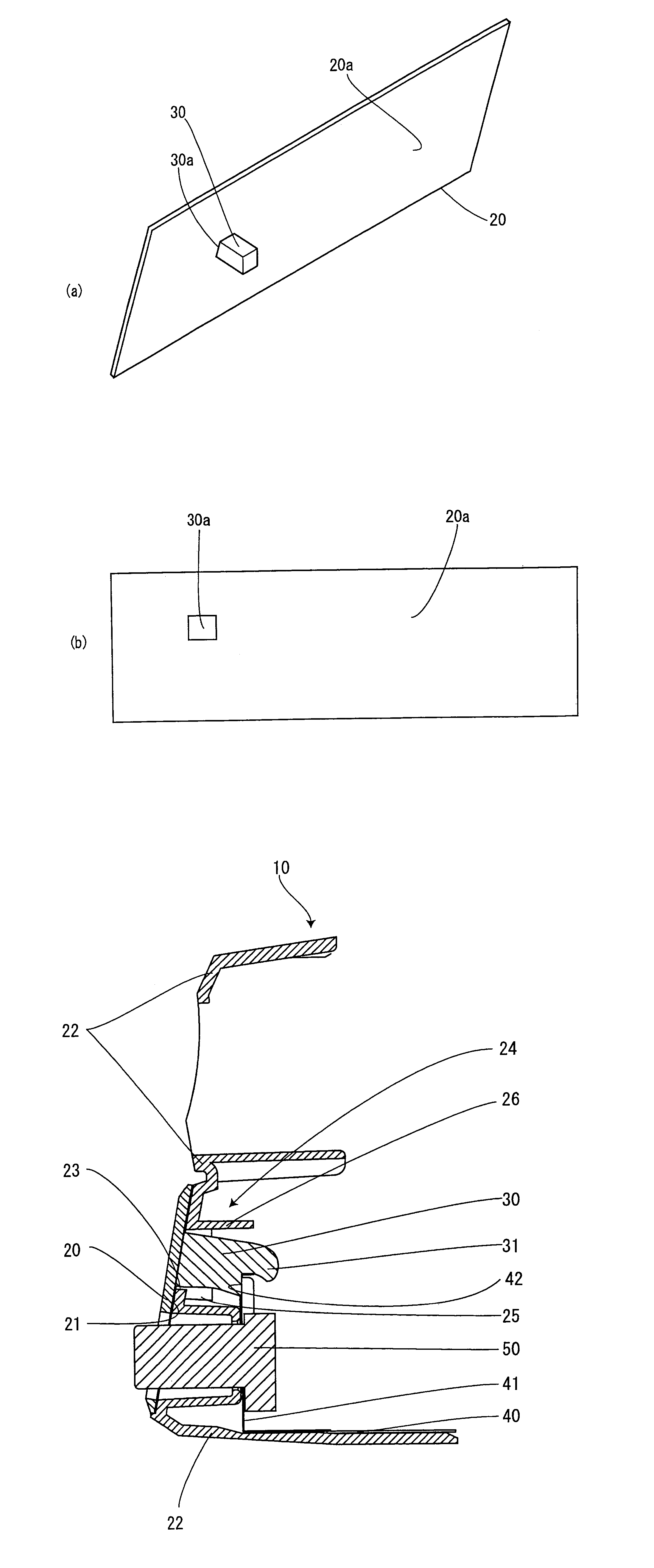
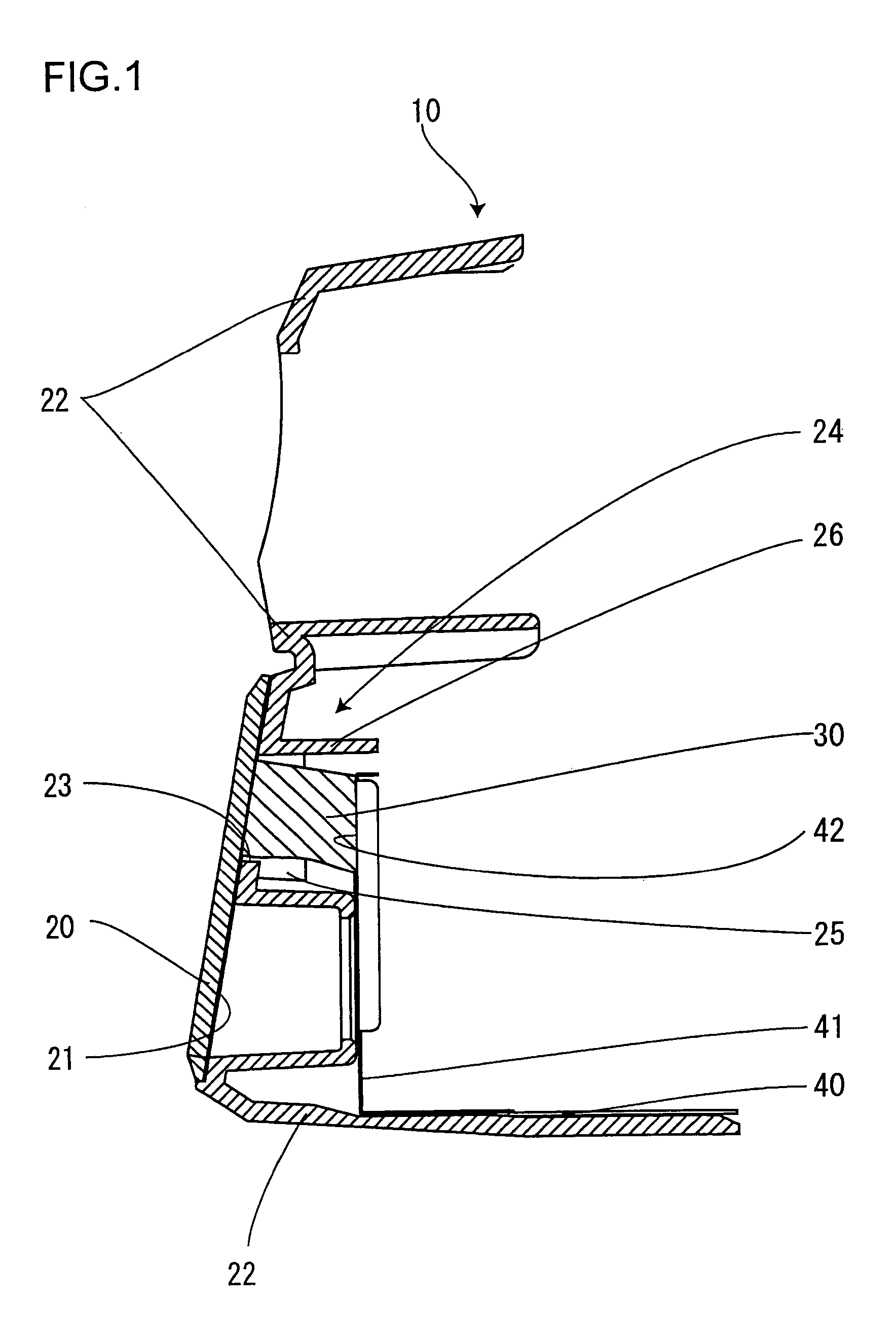
[0026]FIG. 1 is an explanatory cross-sectional view showing a schematic structure of a method for conducting a half mirror and a conductive chassis via an elastic conductive member according to the invention.
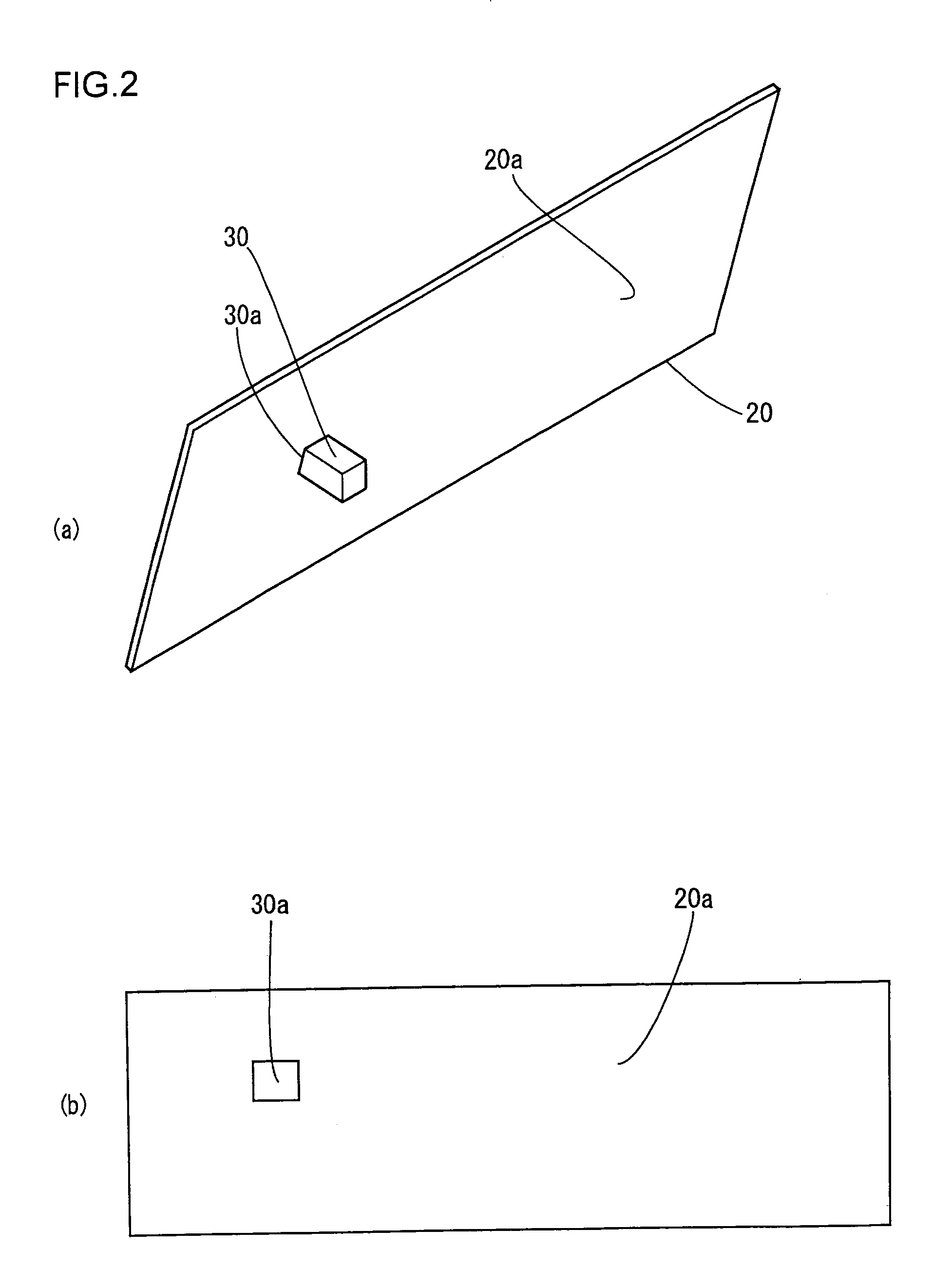
[0027]With reference to FIG. 1, we will explain the structure for providing a ground connection from a half mirror 20 to a conductive chassis 40 so as to prevent static electricity from being charged in the half mirror 20 constituting a part of a decorative panel. The conductive chassis 40 is a metallic panel for mounting a circuit wiring board (not shown) and the like, having an electronic component 50 which is an external connecting terminal such as a jack terminal arranged on a wall surface formed by bending a portion of the conductive chassis upward, and a contact surface 42 to be in contact with an elastic conductive member 30 is arranged on the wall surface of the conductive chassis 40. The elastic conductive member 30 is a conductor for connecting the vapor deposited laye...
second embodiment
[0032]Next, the second embodiment according to the present invention will be described. FIG. 3 is a perspective view showing the through hole and a guide panel provided on a decorative panel through which the elastic conductive member is inserted and supported.
[0033]A through hole 23 for the elastic conductive member 30 is formed to the decorative panel 22, and the decorative panel 22 further has a guide panel 24 projected toward the chassis 40 from the through hole 23. The guide panel 24 has left and right side walls 25 for supporting the left and right sides of the elastic conductive member 30, and an upper wall 26 projected further toward the chassis 40 than the side walls 25. Thus, it becomes possible to pinch using fingers the elastic conductive member 30 from the sides corresponding to the side walls 25, and to insert the member 30 to the hole using the upper wall as a positioning plate defining the vertical position and using the side walls 25 as positioning plates defining t...
PUM
 Abstract
Description
Claims
Application Information
 - R&D
- Intellectual Property
- Life Sciences
- Materials
- Tech Scout
- Unparalleled Data Quality
- Higher Quality Content
- 60% Fewer Hallucinations
Browse by: Latest US Patents, China's latest patents, Technical Efficacy Thesaurus, Application Domain, Technology Topic, Popular Technical Reports.
© 2025 PatSnap. All rights reserved.Legal|Privacy policy|Modern Slavery Act Transparency Statement|Sitemap|About US| Contact US: help@patsnap.com


