System for feeding and transporting documents

a document and document technology, applied in the direction of transportation and packaging, thin material processing, article separation, etc., can solve the problems of large hopper capacity, reduced document stack capacity, and difficulty in consistent presentation, and achieve the effect of reducing the displacement of springs

Inactive Publication Date: 2007-07-03
DIGITAL CHECK CORP
View PDF35 Cites 0 Cited by
  • Summary
  • Abstract
  • Description
  • Claims
  • Application Information

AI Technical Summary

Benefits of technology

[0016]It is, therefore, an object of the invention to provide an improved system for feeding and transporting documents that urges the stack of documents in the hopper toward the feeder in a way that provides consistent presentation of documents to the feeder while addressing the fixed and variable forces encountered in flag travel.
[0019]The fixed force means may take the form of a pulley system and a suspended weight or any other suitable form that directs a generally fixed force to the flag. The spring means may take the form of a pulley system and a spring mounted to a stationary mount from one end or any other suitable form that directs an additive variable spring force to the flag. It is appreciated that the variable force is from a spring means and not from a constant torque or controlled motor; this allows for an entirely mechanical solution. That is, the spring means directs a variable force to the flag so as to urge the document stack with a force that varies with flag position. In this way, each document in the stack may be fed with a force closer to the ideal set of forces because the spring force decreases as the stack size diminishes.
[0020]The fixed force means addresses constant loads encountered by the flag such as bearing drag. The spring means addresses variable loads encountered by the flag such as the friction forces that vary depending on the current number of documents in the stack. Steps may be taken to reduce the overall friction effects such as vibrating the hopper floor.
[0023]In another aspect, a pivoting arm has a first end that is fixed and a second end that is free. The pivoting arm is connected to the flag by the pulley system and the spring has a first end is connected to a fixed mount and a second end connected to the pivoting arm but offset from the pulley system connection to reduce spring displacement with respect to flag displacement.
[0024]In another aspect, the first end of the spring may be connected to any one of a plurality of first spring mount locations on the machine frame. In another aspect, the second end of the spring may be connected to any one of a plurality of second spring mount locations on the pivoting arm. In this way, the orientation of the spring with respect to the pivot arm as well as the attachment point of the spring to the pivot arm with respect to the attachment of the pulley system to the pivot arm may be selected to provide the desired performance needed for the particular implementation.

Problems solved by technology

The difficulty with making hopper capacity larger is one of consistency.
The variety of documents used in different applications make such consistent presentation difficult.
Typically, some form of mechanical intervention urges the document stack along in the hopper but the mechanical intervention may not compensate as the document stack diminishes.
For a large capacity hopper, it is possible that the mechanical intervention may result in correct pinch force when the hopper is full but too much pinch force when the hopper nears empty, or that the mechanical intervention may result in correct pinch force when the hopper is near empty but too little pinch force when the hopper is full.
This form of mechanical intervention may limit the hopper capacity because the applied force to the stack must result in acceptable forces on a feeding document when moving a full hopper of documents and when moving the last few documents.
However, as the number of documents in the hopper decreases, the force required to move them decreases.
Therefore, a constant flag weight is not ideal.
This approach also is not ideal.
The flag also experiences some constant forces such as bearing drag, which a spring does not properly address.
Further, for many hoppers, the need for very long travel and low forces leads to a badly proportioned spring design.
The motor may be provided with feedback from sensors on the feeder mechanism, creating an ideal but complex and more expensive solution.

Method used


Image

  • System for feeding and transporting documents
  • System for feeding and transporting documents
  • System for feeding and transporting documents

Examples


Embodiment Construction

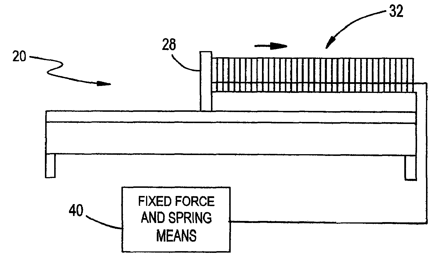
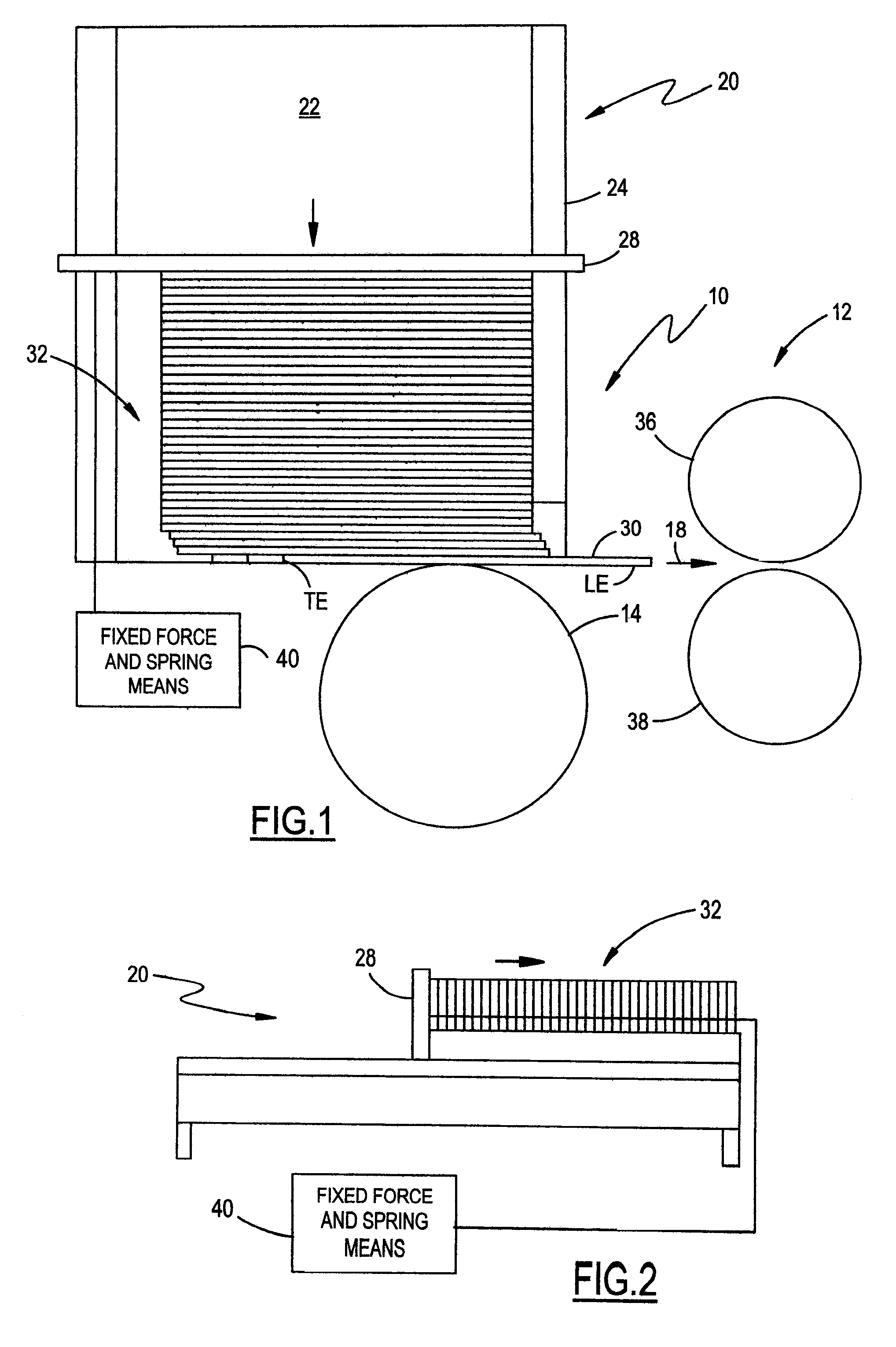
[0028]FIG. 1 illustrates a system for feeding and transporting documents. The system includes a feeder stage 10 and a transport stage 12. The feeder stage 10 includes feeder 14. Transport stage 12 is downstream of feeder stage 10, with arrow 18 pointing in the downstream direction. A document leading edge LE is the more downstream edge while the trailing edge TE is the more upstream edge. Feeder stage 10 further includes hopper assembly 20. Hopper assembly 20 includes a hopper floor 22 and hopper sidewall 24. Hopper assembly 20 further includes document stack supporter or flag 28. A stack 32 of documents engages hopper floor 22. FIG. 2 shows hopper assembly 20 from the side.

[0029]With continuing reference to FIGS. 1 and 2, document stack 32 is shown adjacent to hopper sidewall 24 and includes first document 30 among other documents in stack 32, with the trailing edge TE of first document 30 still in hopper assembly 20. The components shown in FIGS. 1 and 2 are exemplary and alternat...


PUM


Abstract

A system for feeding and transporting documents includes a feeder stage and a transport stage. The hopper assembly includes a hopper floor that carries the document stack and a flag that provides a force to move the documents along the hopper floor toward the feeder. A fixed force means biases the flag with a fixed force while a spring means biases the flag with a variable spring force. The spring force varies with flag position to cause each document in the stack to be fed with an appropriate force due to spring force decreasing as the stack size diminishes.

Description

BACKGROUND OF THE INVENTION[0001]1. Field of the Invention[0002]The invention relates to systems for feeding and transporting documents and to document hoppers used in these systems.[0003]2. Background Art[0004]A typical system for feeding and transporting documents includes a feeder in the document feeding portion of the system, and a series of roller pairs or belts in the document transporting portion of the system. In the feeding portion of the system, the feeder acts to separate and feed documents singly, in order, from a stack. In the transporting portion of the system, the roller pairs and / or belts convey the documents, one at a time, past other processing devices such as readers, printers, and sorters that perform operations on the documents. The feeder is typically a feed wheel, but may take other forms. Further, the components in the transporting portion of the system may take a variety of forms. An existing document feeder is shown in U.S. Pat. No. 6,199,854. That patent d...

Claims


Application Information

Patent Timeline
Patent Type & Authority Patents(United States)
IPC IPC(8): B65H1/02
CPCB65H1/02B65H1/12B65H2402/54B65H2511/152B65H2515/30B65H2220/01B65H2220/08B65H2220/02B65H2511/15
Inventor SPALL, J. MICHAEL
Owner DIGITAL CHECK CORP
Why Eureka
Try Eureka