Test fixture for the aging of wiper blades in a laboratory

a technology for testing fixtures and wiper blades, which is applied in the direction of vehicle cleaning, cleaning equipment, instruments, etc., can solve the problems of inadequate development of process and test fixtures, and achieve the effects of convenient use, convenient use and convenient us

Active Publication Date: 2007-07-03
FORD GLOBAL TECH LLC
View PDF21 Cites 11 Cited by
  • Summary
  • Abstract
  • Description
  • Claims
  • Application Information

AI Technical Summary

Benefits of technology

[0008]It is another object of this invention to provide a test fixture that will incorporate sufficient flexibility to vary the physical environmental parameters under which wiper blades operate in the rear world.
[0020]These and other objects, features and advantages are accomplished according to the instant invention by providing a test fixture for the laboratory testing of windshield wiper blades for vehicles. The test fixture includes a base frame on which are mounted a number of windshield wiper arms oriented generally parallel for engagement with a stainless steel test surface. Positionally adjustable supports are mounted on the base frame to configure the test surface by varying the curvature of the test surface, as well as the overall length thereof, to permit simulation of a large variety of automotive windshields for test purposes. The test fixture also includes a wiper arm mounting device that can be manipulated to vary the wiper arm load to the wiper blade on the test surface. Adjustments in the spring force exerted on the wiper blade allow variances in the application of a biasing force on the wiper blade in conjunction with changes in the attack angle.

Problems solved by technology

Wiper blades are a high use item on automobiles and require frequent replacing during the operative life of an automobile primarily due to the aging of the elastomeric material from which the wiper blade is manufactured.
Historically, such a process and test fixture has not been developed adequately.

Method used


Image

  • Test fixture for the aging of wiper blades in a laboratory
  • Test fixture for the aging of wiper blades in a laboratory
  • Test fixture for the aging of wiper blades in a laboratory

Examples


Embodiment Construction

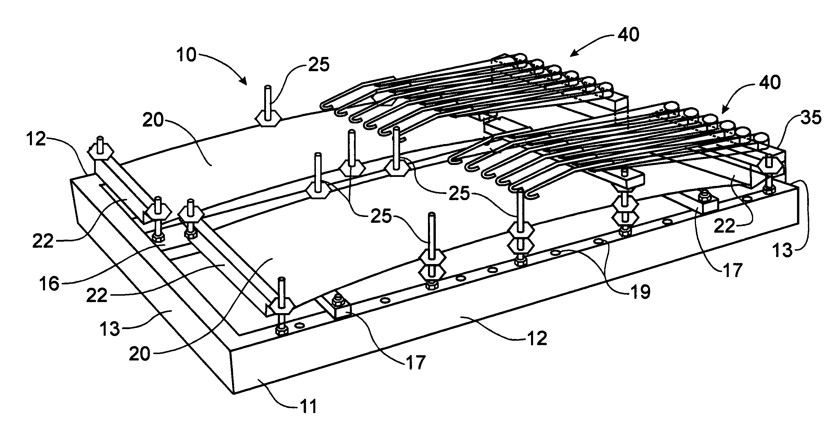
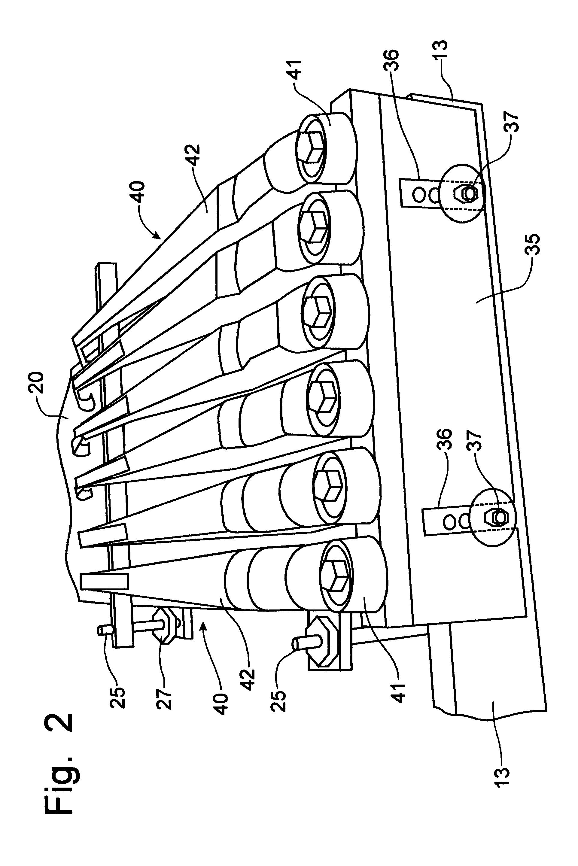
[0032]Referring to FIGS. 1-4, a test fixture for testing wiper blades under laboratory conditions incorporates the principles of the instant invention. The test fixture 10 includes a frame 11 preferably manufactured from aluminum and formed from a pair of side beams 12 and a pair of end beams 13 with four upright support posts 14 positioned near the four corners of the rectangular frame 11. The upright support posts 14 are utilized, as is depicted in FIG. 9 to stack multiple test fixtures; therefore, the upright posts 14 have to be configured to be stackable such as by having the upper ends of the posts 14 sized to fit within the bottom ends of the posts 14.

[0033]The rectangular frame 11 is formed with a center support beam 16 that is oriented parallel to the side beams 12 and located midway between the side beams 12 to provide support for the plates 20 that provide a test surface against which the wiper blades will be engaged, as will be described in greater detail below. The frame...


PUM


Abstract

A test fixture facilitates the laboratory testing of windshield wiper blades for vehicles. The test fixture includes a base frame on which are mounted a number of windshield wiper arms oriented generally parallel for engagement with a stainless steel test surface. Positionally adjustable supports are mounted on the base frame to configure the test surface by varying the curvature of the test surface, as well as the overall length thereof, to permit simulation of a large variety of automotive windshields for test purposes. The test fixture also includes a wiper arm mounting device that can be manipulated to vary the wiper arm load to the wiper blade on the test surface. Adjustments in the spring force exerted on the wiper blade allow variances in the application of a biasing force on the wiper blade in conjunction with changes in the attack angle.

Description

CROSS-REFERENCE TO RELATED APPLICATIONS[0001]This application claims domestic priority on U.S. Provisional Patent Application Ser. No. 60 / 638,050, filed on Dec. 21, 2004, the contents of which are incorporated herein by reference.FIELD OF THE INVENTION[0002]This invention relates to a device for testing wiper blades for automobiles and, more particularly, to a fixture for aging wiper blades to replicate the real world environment to which wiper blades are exposed.BACKGROUND OF THE INVENTION[0003]Wiper blades are a high use item on automobiles and require frequent replacing during the operative life of an automobile primarily due to the aging of the elastomeric material from which the wiper blade is manufactured. Aging of the wiper is a function of the exposure of the wiper blade to the environment and of the external forces exerted on the wiper blade from the mounting arms and the curvature of the windshield glass over which the wiper blade is operated.[0004]To develop improved wipe...

Claims


Application Information

Patent Timeline
IPC IPC(8): G01M19/00G01N3/56A47L1/02G01M99/00
CPCB60S1/3429B60S1/347G01M99/007B60S1/0469G01N2203/0246
Inventor PERIN, GIOVANNI
Owner FORD GLOBAL TECH LLC
Why Eureka
Try Eureka