
Methods of orienting an easy axis of a high-aspect ratio write head for improved writing efficiency

a technology of high-aspect ratio and easy axis, which is applied in the direction of assembling head elements, magnetic recording, information storage, etc., can solve the problems of stress-anisotropy in the pole tip region, and the “easy axis” of conventional magnetic field plating/annealing, etc., to facilitate more efficient switching in the write head

Inactive Publication Date: 2007-07-03
HITACHI GLOBAL STORAGE TECH NETHERLANDS BV
View PDF2 Cites 71 Cited by
  • Summary
  • Abstract
  • Description
  • Claims
  • Application Information

AI Technical Summary

Benefits of technology

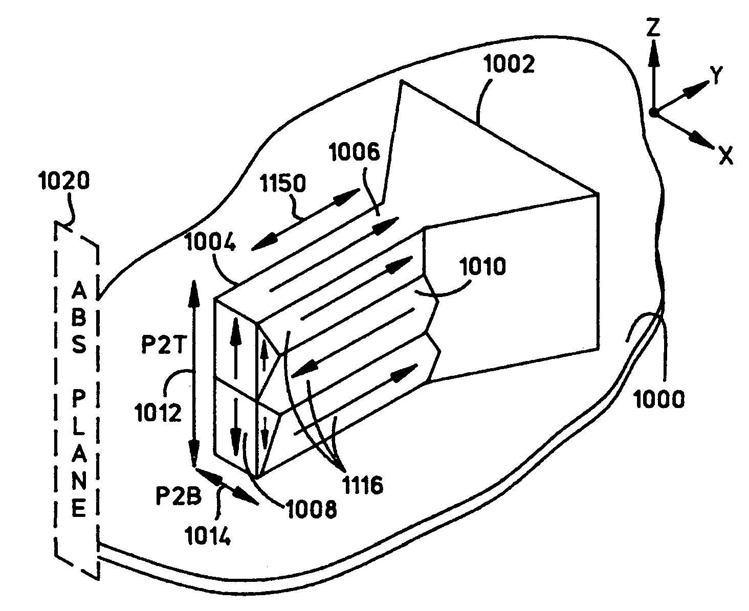
[0007]A pole piece of a magnetic write head is formed over a substrate and includes a pole tip having a width that is less than its height which is normal the substrate. Due to stress-anisotropy, the pole tip structure has an inherent easy-axis which is oriented in an unfavorable direction (i.e. perpendicular to the ABS and almost collinear with a driving field of the write head). To alleviate this problem, during electroplating or annealing of the pole piece a magnetic field is applied to the pole tip in a direction which is out-of-plane from the substrate but in-plane with a side wall of the pole tip which vertically projects from the substrate. By applying the magnetic field in this manner, the easy axis of the pole piece is oriented in the direction of the applied magnetic field to facilitate more efficient switching in the write head. Ideally, the angle θ is about 90° for Hexagonal-Closed Packed (HCP) materials or about 50° for Face-Centered Cubic or Body-Centered Cubic (BCC) materials (e.g. NiFe and CoFe).

Problems solved by technology

It has been discovered that conventional magnetic field plating / annealing does not properly set the “easy axis” of pole tips having such high-aspect-ratios.
Stress in such pole tips materials is high which causes stress-anisotropy in the pole tip region.

Method used


Image

  • Methods of orienting an easy axis of a high-aspect ratio write head for improved writing efficiency
  • Methods of orienting an easy axis of a high-aspect ratio write head for improved writing efficiency
  • Methods of orienting an easy axis of a high-aspect ratio write head for improved writing efficiency

Examples


Embodiment Construction

[0028]A pole piece of a magnetic write head is formed over a substrate and includes a pole tip having a width that is less than its height which is normal the substrate. Due to stress-anisotropy, the pole tip structure has an inherent easy-axis which is oriented in an unfavorable direction (i.e. perpendicular to the ABS and almost collinear with a driving field of the write head). To alleviate this problem, during electroplating or annealing of the pole piece a magnetic field is applied to the pole tip in a direction which is out-of-plane from the substrate but in-plane with a side wall of the pole tip which vertically projects from the substrate. By applying the magnetic field in this manner, the easy axis of the pole piece is oriented in the direction of the applied magnetic field to facilitate more efficient switching in the write head. Ideally, the angle θ is about 90° for Hexagonal-Closed Packed (HCP) materials or about 50° for Face-Centered Cubic or Body-Centered Cubic (BCC) m...


PUM

PropertyMeasurementUnit
angleaaaaaaaaaa
angleaaaaaaaaaa
angleaaaaaaaaaa

Abstract

A pole piece of a magnetic write head is formed over a substrate and includes a pole tip having a width that is less than its height which is normal the substrate. Due to stress-anisotropy, the pole tip structure has an inherent easy-axis which is oriented in an unfavorable direction (i.e. perpendicular to the ABS and almost collinear with a driving field of the write head). To alleviate this problem, during electroplating or annealing of the pole piece a magnetic field is applied to the pole tip in a direction which is out-of-plane from the substrate but in-plane with a side wall of the pole tip which vertically projects from the substrate. By applying the magnetic field in this manner, the easy axis of the pole piece is oriented in the direction of the applied magnetic field to facilitate more efficient switching in the write head. Ideally, the angle θ is about 90° for Hexagonal-Closed Packed (HCP) materials or about 50° for Face-Centered Cubic or Body-Centered Cubic (BCC) materials (e.g. NiFe and CoFe).

Description

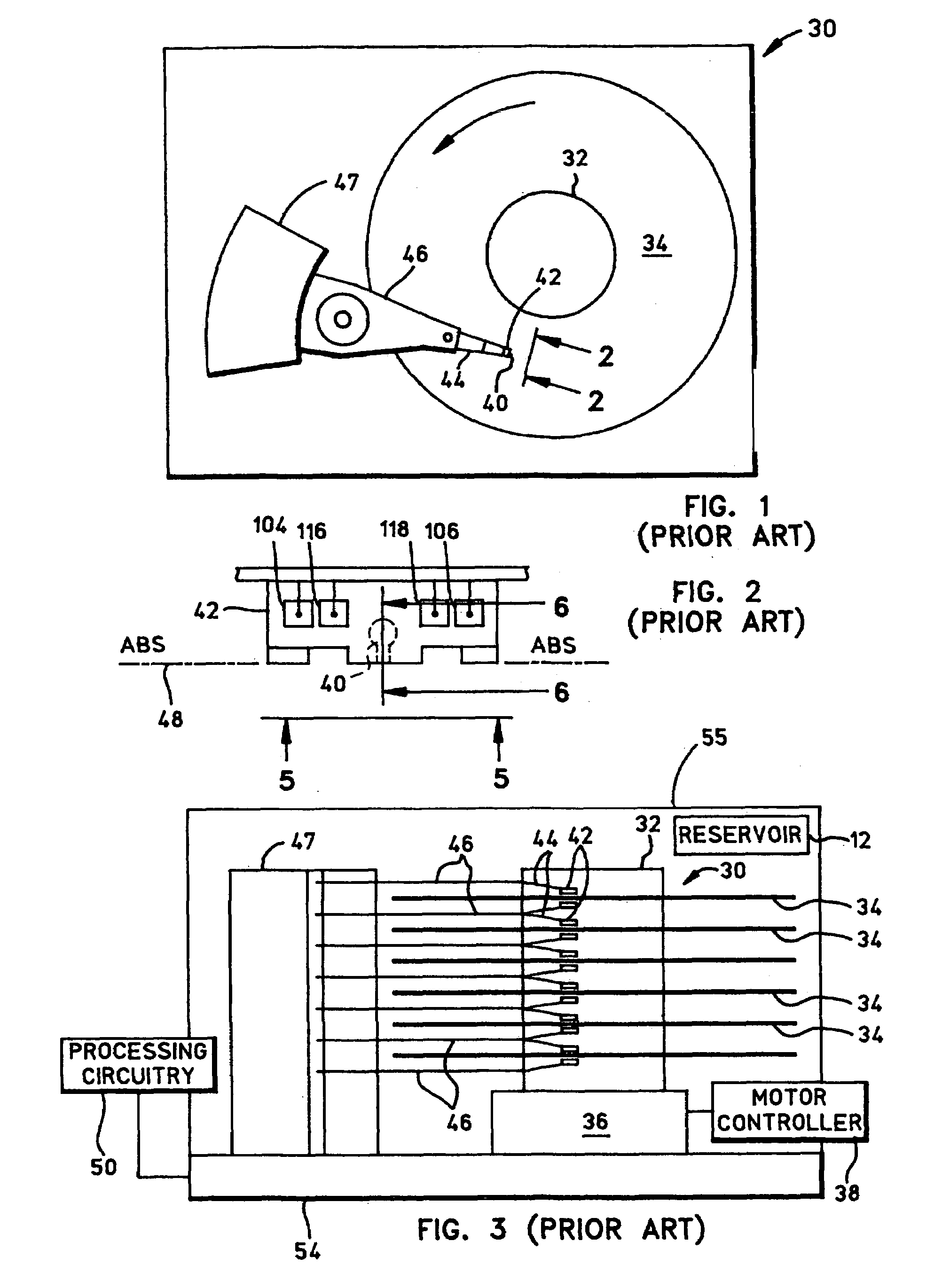
BACKGROUND OF THE INVENTION[0001]1. Field of the Invention[0002]This invention relates generally to methods of orienting an easy axis of a high-aspect-ratio pole piece of a magnetic write head, and more particularly relates to methods of making a magnetic write head which include forming a pole piece over a substrate and applying a magnetic field to a pole tip of the pole piece in a direction forming an angle that is out-of-plane from the substrate and in-plane with a side wall of the pole piece which vertically projects from the substrate.[0003]2. Description of the Related Art[0004]Computers often include auxiliary memory storage devices having media on which data can be written and from which data can be read for later use. A direct access storage device (disk drive) incorporating rotating magnetic disks are commonly used for storing data in magnetic form on the disk surfaces. Data is recorded on concentric, radially spaced tracks on the disk surfaces using a magnetic head which ...

Claims


Application Information

Patent Timeline
Patent Type & Authority Patents(United States)
IPC IPC(8): G11B5/127
CPCG11B5/1272Y10T29/49032Y10T29/49034Y10T29/49021
Inventor LAM, QUAN-CHIU HARRY
Owner HITACHI GLOBAL STORAGE TECH NETHERLANDS BV
Learn More