
Method for simulating a mechatronic system

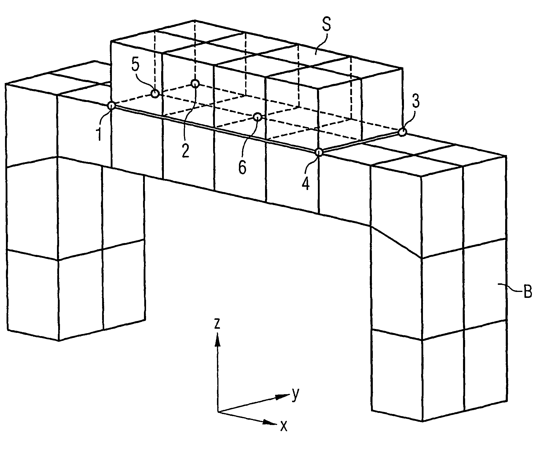
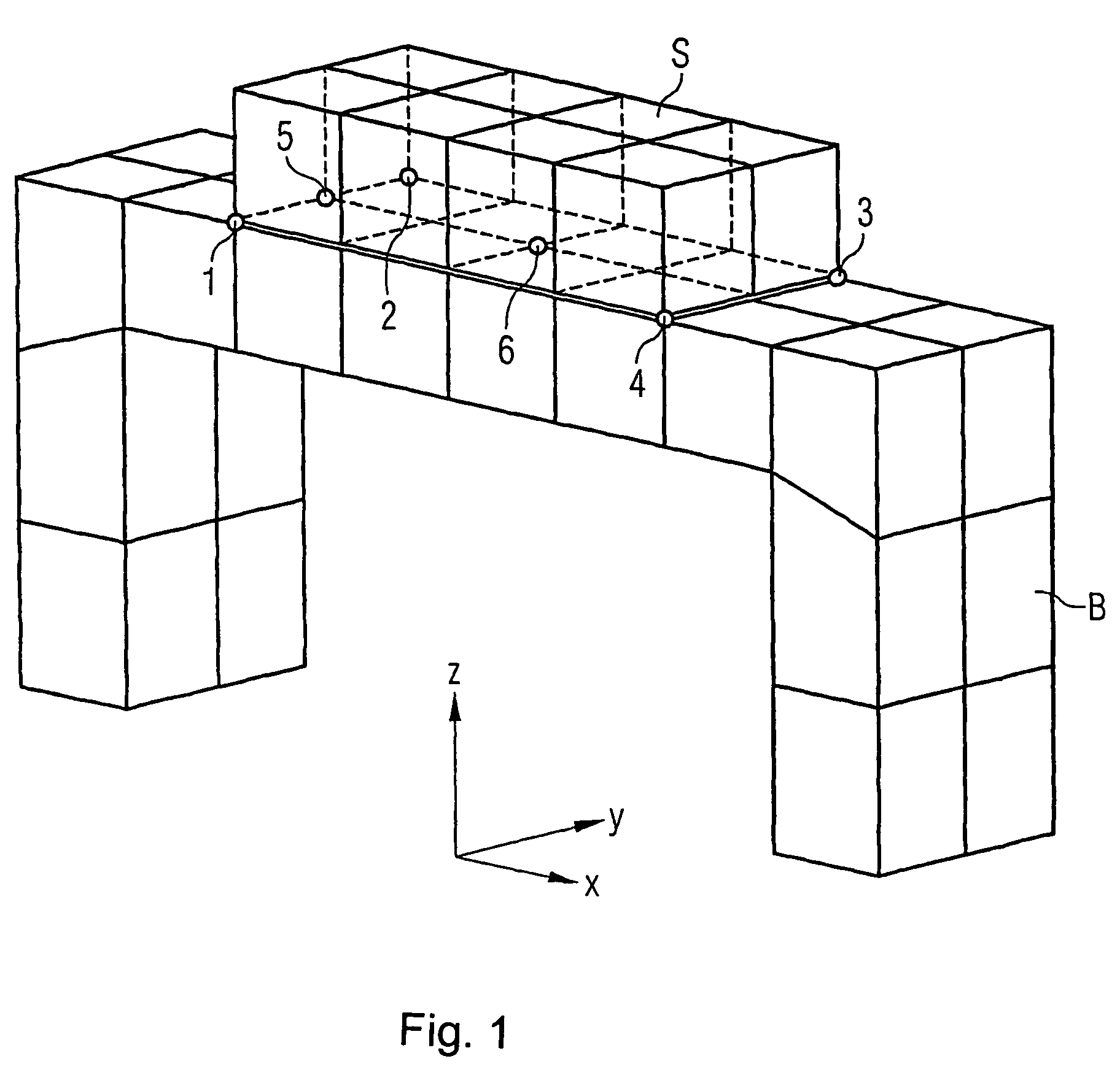
a mechatronic system and simulation method technology, applied in the field of mechatronic system simulation, can solve the problems of consuming a lot of time, and achieve the effect of reducing the need for calculation and increasing the simulation accuracy

Inactive Publication Date: 2007-06-26
SIEMENS AG
View PDF8 Cites 5 Cited by
  • Summary
  • Abstract
  • Description
  • Claims
  • Application Information

AI Technical Summary

Benefits of technology

[0013]It is therefore an object of the invention, to provide a method of the afore-stated type that has a reduced need for calculation and increased accuracy of simulation compared to afore-illustrated conventional methods.
[0018]According to a first advantageous embodiment of the method of the present invention, the fundamental motion equation is transformed into first order linear differential equations in the modal space. In this way, it is possible to select or deselect predeterminable eigenmodes before carrying out a time discretization.
[0020]Of course, there is also the possibility to incorporate additional forces in the system without time delay, when required by the actual situation (e.g. simulation of gravity). This is preferably realized by considering additional non-time-delayed forces {right arrow over (F)}D in the system by splitting the force vector {right arrow over (F)} into a contribution from forces {right arrow over (F)}R with a time delay and a contribution from forces {right arrow over (F)}D without a time delay when determining the time response of the system.

Problems solved by technology

In order to solve the fundamental motion equation (1), diverse time integration processes are used which are enormously time consuming because the width of the integration step has to be selected small enough to maintain an integration error within acceptable limits to satisfy the demand on the accuracy.

Method used


Image

  • Method for simulating a mechatronic system
  • Method for simulating a mechatronic system
  • Method for simulating a mechatronic system

Examples


Embodiment Construction

[0033]In accordance with the invention, the fundamental motion equation (1) described above is initially transformed into normal standard state equations, in particular into first order linear differential equations, preferably in the modal space. These equations are subsequently discretized with respect to time so that only algebraic difference equations instead of the differential equations have to be solved to determine the time response of the system. This can be implemented with current computer systems in a simple and effective manner.

[0034]With this transformation, the time response of the simulated system can be determined by actualizing the time raster, i.e. the calculation of the difference equations, only in the sampling raster of the control processor. This is the case because only the values in the clock cycle of a computer that executes the calculation are relevant. The calculating step width can thus be reduced from typically between 1 and 5 msec to 100 μsec, dependin...


PUM


Abstract

According to the invention, a simulation is carried out based on the fundamental motion equation (1) for simulating the system by means of: transformation of the fundamental motion equation into linear differential equations of the first order; further transformation of the linear differential equations into time-discrete state variables; determination of the time response of the system by actualization of the resulting algebraic differential equations in the sampling raster of an associated control processor. Higher simulation accuracy is obtained at an essentially smaller calculating capacity.

Description

BACKGROUND OF THE INVENTION[0001]The invention relates to a method for simulation of mechatronic systems.[0002]Mechatronic systems of this type include at least one mechanical and electrotechnical / electronic component combined to a unitary system as far as construction, configuration and operation are concerned. This fact is known under the term “mechatronic”.[0003]Conventionally, simulation of a mechanism is implemented either through application of multi-mass models, i.e. models with concentrated springs and masses whose differential equations are formed quasi “by hand”, or preferably with so-called FEM models. Such FEM models or finite-element models are preferred in view of their greater accuracy, however they involve highly complex calculations.[0004]In the latter case, a fundamental equation of motion is as follows:M·{right arrow over (ü)}+D·{right arrow over ({dot over (u)}(t)+C·{right arrow over (u)}(t)={right arrow over (F)}(t)  (1)wherein[0005]M is the mass matrix,[0006]D ...

Claims


Application Information

Patent Timeline
IPC IPC(8): G06G7/48G05B13/04G05B17/02G06F17/13
CPCG05B17/02
Inventor HAMM, CARSTENLOUIS, MICHAELPAPIERNIK, WOLFGANG
Owner SIEMENS AG
Learn More