
Liquid crystal panel and liquid crystal display apparatus

a liquid crystal display and liquid crystal panel technology, applied in non-linear optics, instruments, optics, etc., can solve the problems of reducing the contrast ratio in an oblique direction, the display apparatus cannot operate at high temperatures, and the display properties are deteriorated, so as to prevent uneven retardation values and small photoelastic coefficients , excellent display uniformity

Active Publication Date: 2007-06-26
NITTO DENKO CORP
View PDF17 Cites 12 Cited by
  • Summary
  • Abstract
  • Description
  • Claims
  • Application Information

AI Technical Summary

Benefits of technology

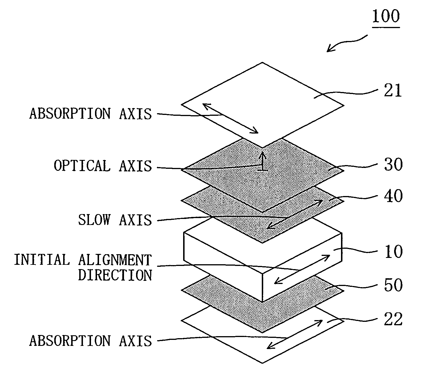
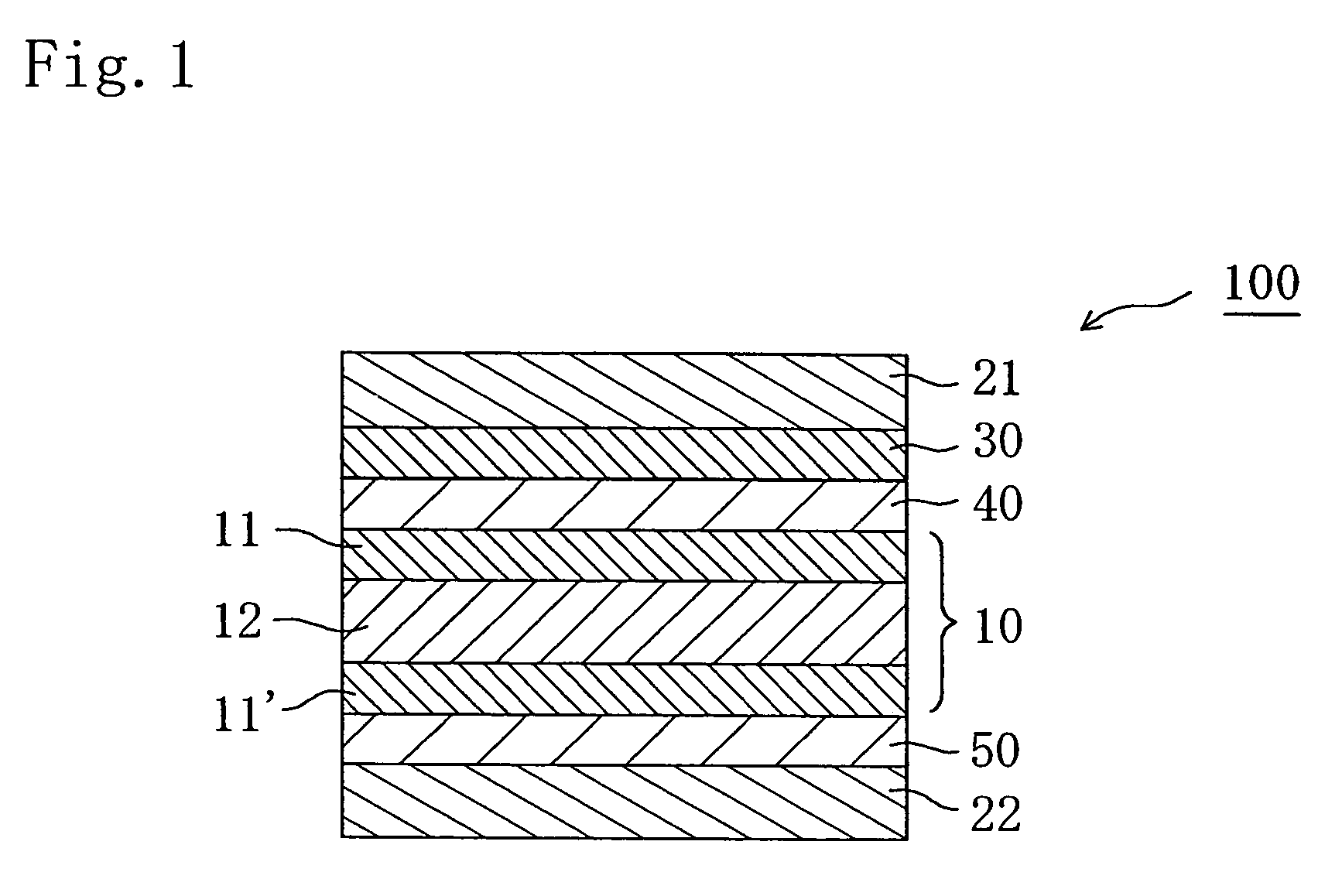
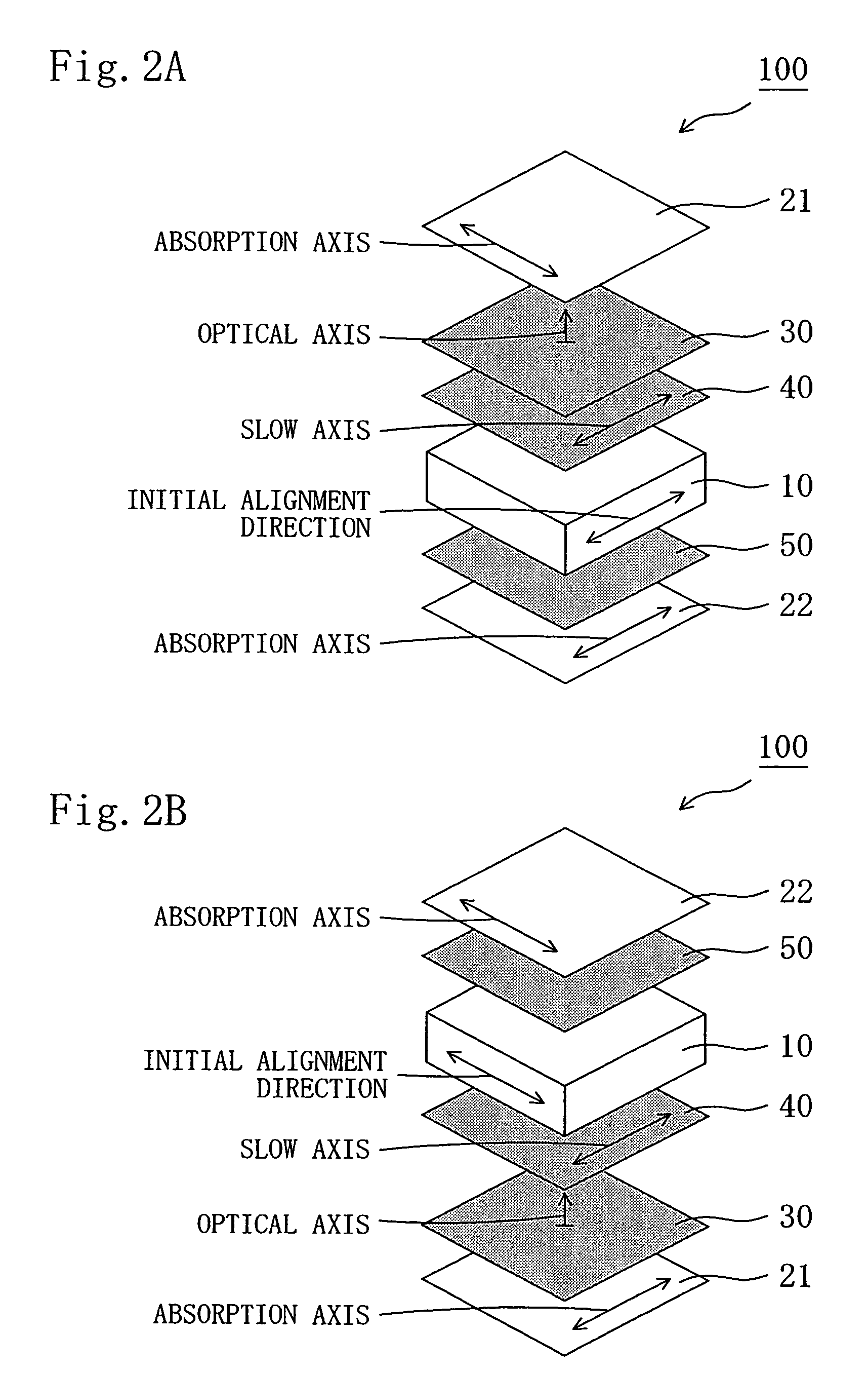
The present invention relates to a liquid crystal panel and a liquid crystal display apparatus. The invention includes a liquid crystal cell with a specific arrangement of optical elements to improve display properties. The first optical element has a negative uniaxial property, and the second optical element satisfies specific expressions. The third optical element has optical isotropy. The invention also includes a refractive index profile of the liquid crystal layer, and a slow axis of the second optical element. The invention can increase the contrast ratio and reduce color shift in an oblique direction.

Problems solved by technology

The use of the liquid crystal display apparatus has spread because disadvantages in that its display properties vary depending on an angle from which a screen is viewed and that the liquid crystal display apparatus cannot operate at high temperatures and very low temperatures have been overcome by technical innovations.
However, a conventional liquid crystal display apparatus provided with a liquid crystal cell of IPS mode has problems of deterioration in display properties such as: a reduced contrast ratio in an oblique direction; and variation in coloring (also referred to as color shift in an oblique direction) of images depending on a viewing angle.
However, the disclosed technique provides insufficient improvement in contrast ratio in an oblique direction and color shift in an oblique direction, and further improvement in display properties is desired.
Thus, the aromatic polymer film has a problem in that display evenness degrades as described below.
Further, uneven stress generated by heat of backlight may cause unevenness in retardation values.
However, such a film hardly causes retardation, and desired retardation values cannot be obtained through stretching at a low stretch ratio as in the aromatic polymer film, or even at a high stretch ratio.
The stretching at a high stretch ratio causes a problem of breaking of the film.

Method used


Image

  • Liquid crystal panel and liquid crystal display apparatus
  • Liquid crystal panel and liquid crystal display apparatus
  • Liquid crystal panel and liquid crystal display apparatus

Examples


reference example 1

[0288]A polymer film “9P75R” (trade name, thickness of 75 μm, average degree of polymerization of 2,400, degree of saponification of 99.9 mol %, available from Kuraray Co., Ltd.) containing polyvinyl alcohol as a main component was uniaxially stretched 2.5 times by using a roll stretching machine while the polymer film was colored in a coloring bath maintained at 30° C.±3° C. and containing iodine and potassium iodide. Next, the polymer film was uniaxially stretched to a 6 times length of the original length of the polyvinyl alcohol film in a bath maintained at 60° C.±3° C. and containing an aqueous solution of boric acid and potassium iodide while a crosslinking reaction was performed. The obtained film was dried in an air circulating thermostatic oven at 50° C.±1° C. for 30 min, to thereby obtain polarizers P1 and P2 each having a moisture content of 26%, a thickness of 28 μm, a degree of polarization of 99.9%, and a single axis transmittance of 43.5%.

Production of First Optical E...

reference example 2

[0289]A polymer film “UZ-TAC” (trade name, thickness of 40 μm, average refractive index of 1.48, available from Fuji Photo Film Co., Ltd.) containing triacetyl cellulose as a main component was used as it is as a retardation film 1-A. Table 1 collectively shows properties of the retardation film 1-A and properties of a film of Reference Example 3 described below.

[0290]

TABLE 1ReferenceReferenceExample 2Example 3Retardation film1-A1-BThickness(μm)4080Transmittance (%)9191Re[590](nm)0.30.8Rth[590](nm)40.160.5C[590]× 10−12(m2 / N)17.817.5

reference example 3

[0291]A polymer film “UZ-TAC” (trade name, thickness of 80 μm, average refractive index of 1.48, available from Fuji Photo Film Co., Ltd.) containing triacetyl cellulose as a main component was used as it is as a retardation film 1-B. Table 1 shows the properties of the retardation film 1-B.

Production of Second Optical Element


PUM

PropertyMeasurementUnit
thickness direction retardationaaaaaaaaaa
thicknessaaaaaaaaaa
thickness direction retardationaaaaaaaaaa

Abstract

There is provided a liquid crystal panel having an improved contrast ratio in an oblique direction and an improved color shift in an oblique direction. Further, there is provided a liquid crystal panel with excellent display uniformity. The liquid crystal panel of the present invention includes: a liquid crystal cell; a first polarizer arranged on one side of the liquid crystal cell; a second polarizer arranged on the other side of the liquid crystal cell; a first optical element and a second optical element arranged between the first polarizer and the liquid crystal cell; and a third optical element arranged between the second polarizer and the liquid crystal cell, in which: the first optical element has substantially optically negative uniaxial property; the second optical element satisfies the following expressions (1) and (2) and is arranged between the first optical element and the liquid crystal cell; and the third optical element has substantially optical isotropy.130 nm≦Re[590]≦250 nm   (1)0 nm<Rth[590]<Re[590].  (2)

Description

[0001]This application claims priority under 35 U.S.C. Section 119 to Japanese Patent Application No. 2004-367040 filed on Dec. 20, 2004 and Japanese Patent Application No. 2005-190515 filed on Jun. 29, 2005, which are herein incorporated by reference.FIELD OF THE INVENTION[0002]The present invention relates to a liquid crystal panel having a liquid crystal cell, a polarizer, and an optical element. Further, the present invention relates to a liquid crystal television and a liquid crystal display apparatus both using the liquid crystal panel.DESCRIPTION OF THE RELATED ART[0003]A liquid crystal display apparatus has attracted attention for its properties such as being thin, being lightweight, and having low power consumption, and is widely used in: portable devices such as a cellular phone and a watch; office automation (OA) devices such as a personal computer monitor and a laptop personal computer; and home appliances such as a video camera and a liquid crystal television. The use o...

Claims


Application Information

Patent Timeline
Patent Type & Authority Patents(United States)
IPC IPC(8): G02F1/1335
CPCG02F1/133634G02F1/13363
Inventor YODA, KENJIYANO, SHUUJIHAYASHI, MASAKI
Owner NITTO DENKO CORP
Learn More