
Steer-by-wire system and control program therefor

a technology of steering handle and control program, which is applied in the direction of steering initiation, instruments, vessel construction, etc., can solve the problem of excessive turning of the steering handle by the vehicle driver, and achieve the effect of preventing excessive turning of the steering handl

Active Publication Date: 2007-06-26
JTEKT CORP
View PDF13 Cites 24 Cited by
  • Summary
  • Abstract
  • Description
  • Claims
  • Application Information

AI Technical Summary

Benefits of technology

[0008]Accordingly, in view of the foregoing drawback, it is a primary object of the present invention to provide an improved steer-by-wire system and an improved control program therefor which are capable of preventing a steering handle from being turned excessively.
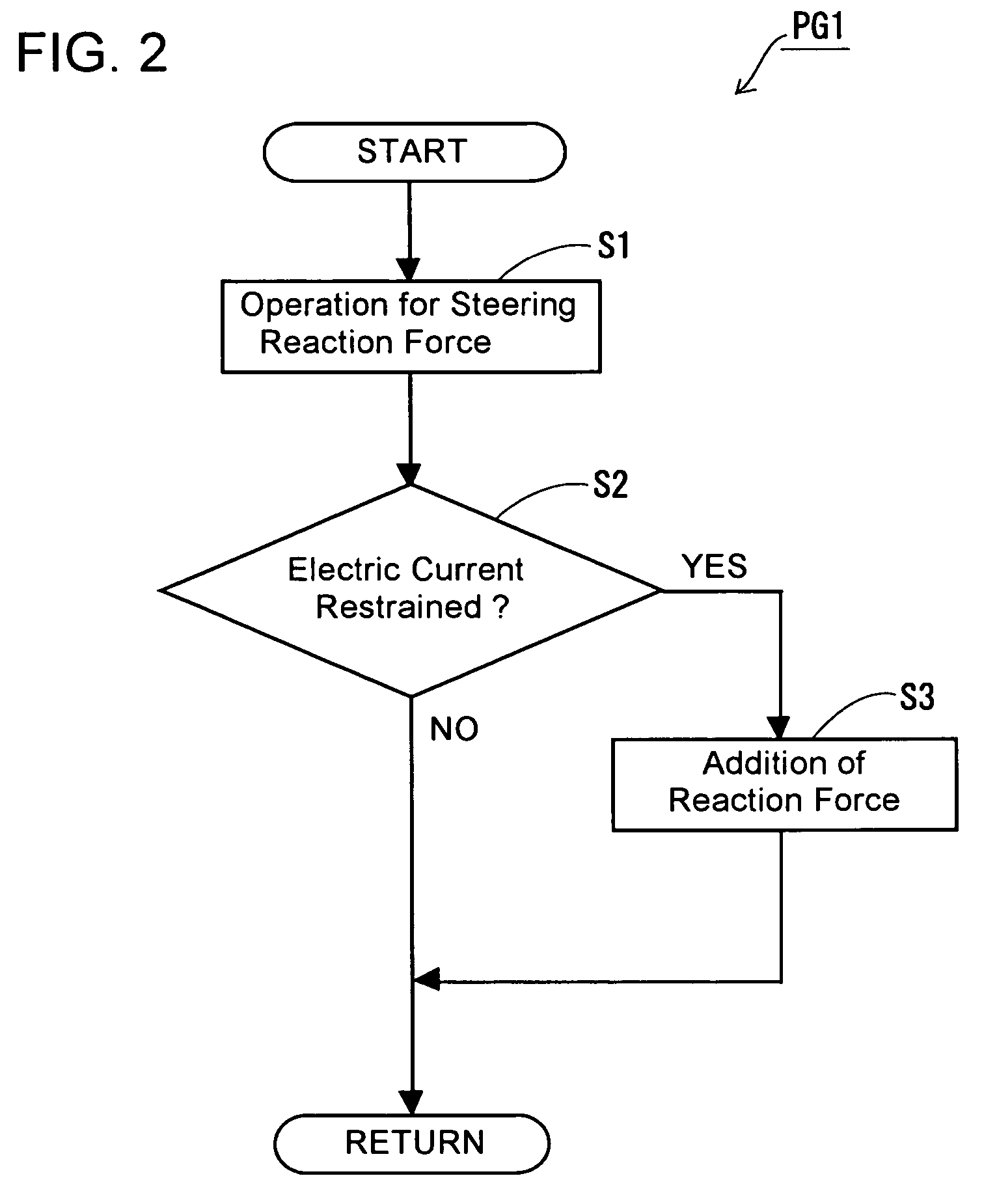
[0010]With this configuration, in the ordinary state, the reaction force generating actuator is driven to make the steering reaction force correspond to the drive electric current to the steering actuator. However, while the drive electric current to the steering actuator is restrained, the reaction force generating actuator is driven to increase the steering reaction force thereby to make the steering handle hard to turn, so that the same can be prevented from being turned excessively.
[0012]According to the control program of this configuration, while the drive electric current to the steering actuator is restrained, the steering reaction force is increased to make the steering handle hard to turn further. Thus, the steering handle can be prevented from being steered excessively as is the case of the prior art system. Further, while the drive electric current to the steering actuator is restrained, the ratio of the steering angle of the steerable road wheels to the steering angle of the steering handle is made smaller than that in the ordinary state. Therefore, the steering handle becomes hard to turn further, from the fact of which the vehicle driver can be notified that the drive electric current to the steering actuator is restrained.

Problems solved by technology

However, in the steer-by-wire system under development, the steering reaction force is controlled to be decreased as the drive electric current to the steering actuator is limited or restrained, and it occurs therefore that the vehicle driver turns the steering handle excessively even in the state that the steerable road wheels are unable to steer further.

Method used


Image

  • Steer-by-wire system and control program therefor
  • Steer-by-wire system and control program therefor
  • Steer-by-wire system and control program therefor

Examples


Embodiment Construction

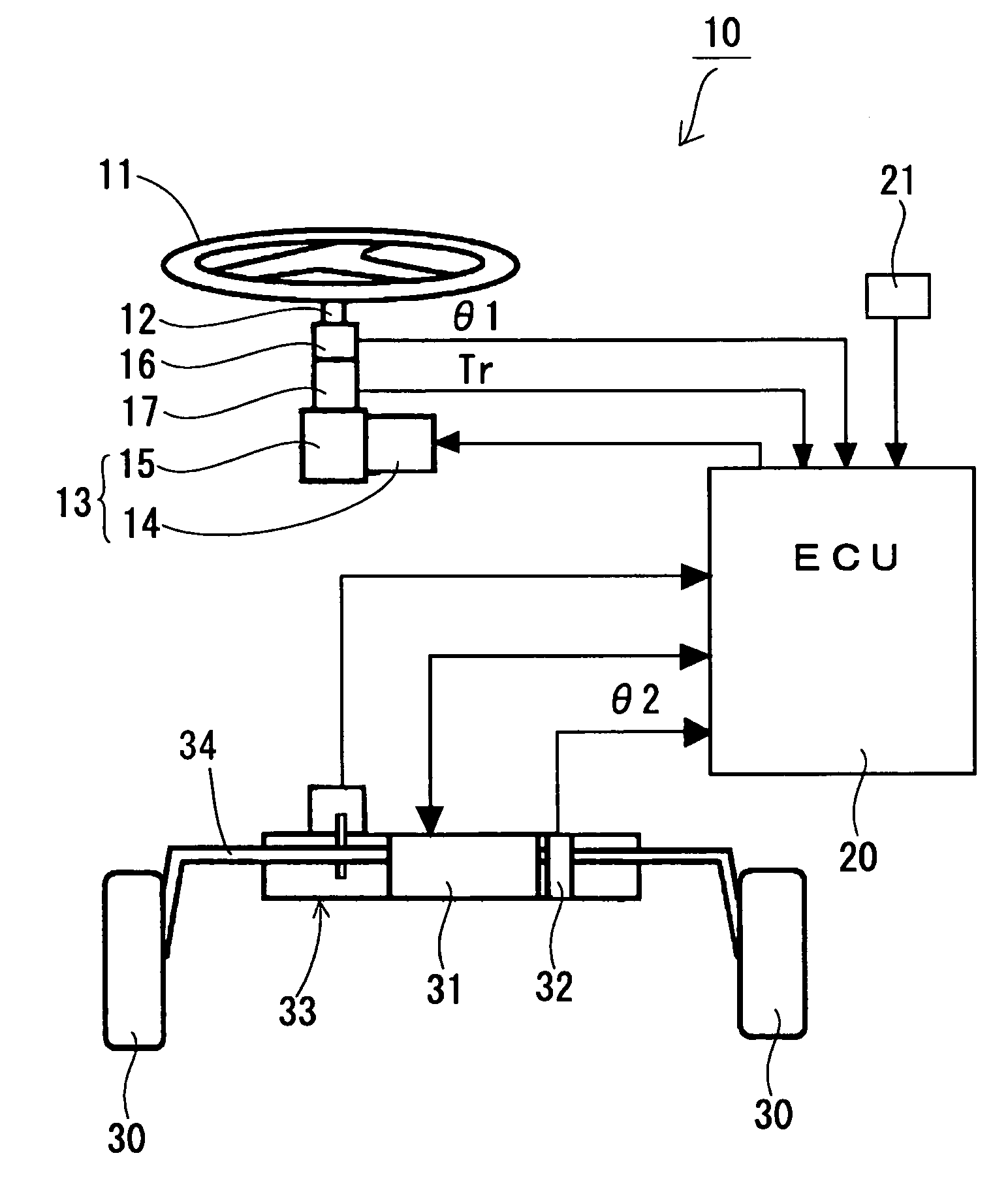
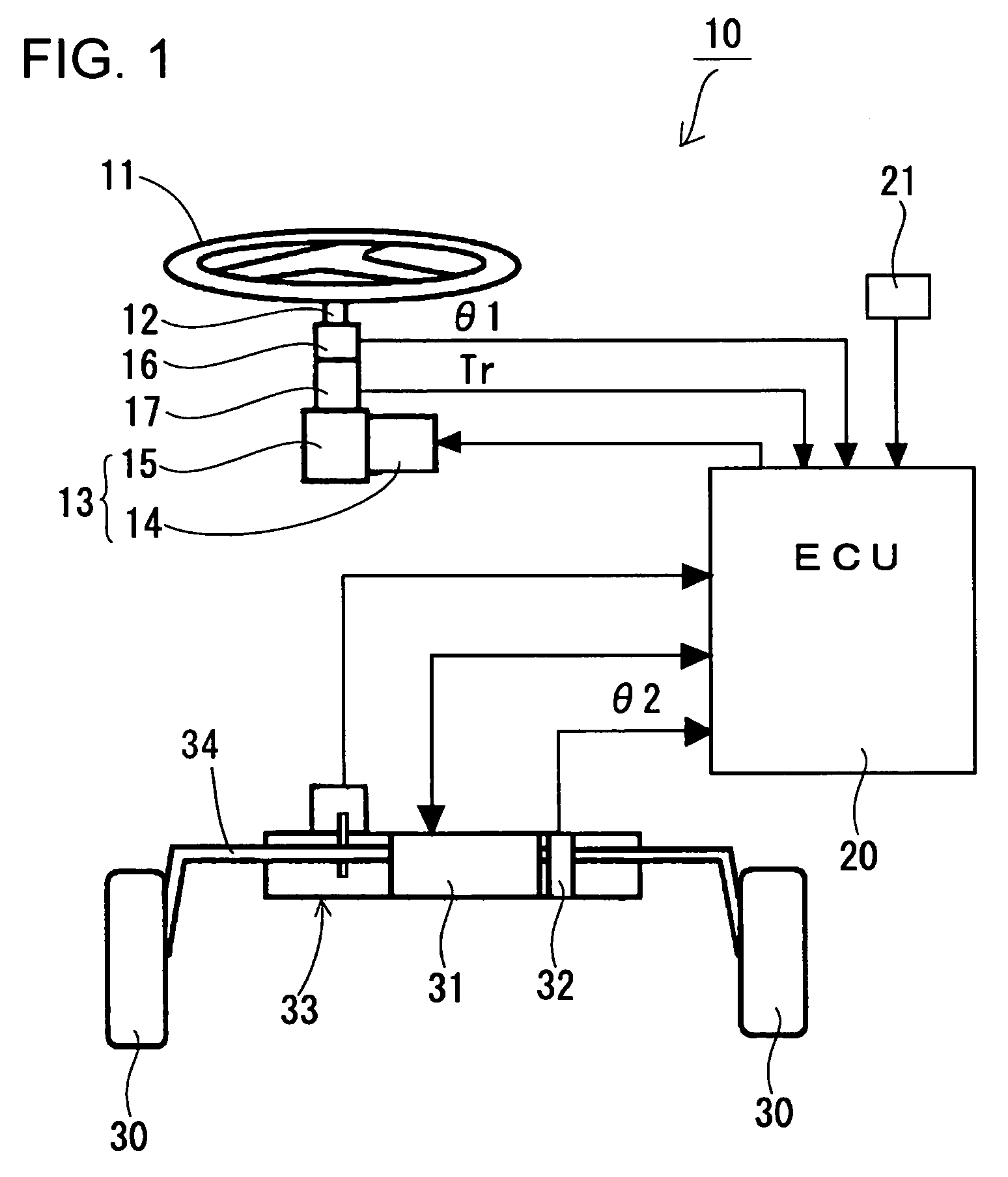
[0017]An embodiment according to the present invention will be described hereafter with reference to FIGS. 1 to 3. FIG. 1 shows the general construction of a steer-by-wire system 10 in one embodiment according to the present invention. In this steer-by-wire system 10, a steering handle 11 is mechanically disconnected from steerable road wheels 30 (usually, front wheels of a vehicle), and a reaction force generating actuator 13 is connected to an end of a steering shaft 12 extending from the center of the steering handle 11. The reaction force generating actuator 13 is composed of an electric motor 14 and a worm gear mechanism 15. The motor 14 is arranged with its rotational shaft extending perpendicular to the steering shaft 12, and the worm gear mechanism 15 is constituted as of the type that a worm shaft (not shown) secured on the rotational shaft of the electric motor 14 is in meshing engagement with a worm wheel (not shown) secured on the steering shaft 12.

[0018]On the intermedi...


PUM


Abstract

Disclosed is a steer-by-wire system and a control program therefor which are capable of preventing a steering handle from being turned excessively. According to the steer-by-wire system and the control program, when drive electric current to a steering actuator is restrained to restrict the steering of steerable road wheels, the steering reaction force to the steering handle is increased thereby to make the steering handle hard or unable to turn further. Thus, the steering handle can be prevented from being turned excessively. Further, when the steering actuator is heated beyond a predetermined temperature, such is judged as the overload on the steering actuator thereby to restrain the drive electric current to the steering actuator. Therefore, it can be obviated that the steering actuator is overheated to suffer failure.

Description

INCORPORATION BY REFERENCE[0001]This application is based on and claims priority under 35 U.S.C. sctn. 119 with respect to Japanese Application No. 2003-116784 filed on Apr. 22, 2003, the entire content of which is incorporated herein by reference.BACKGROUND OF THE INVENTION[0002]1. Field of the Invention[0003]The present invention relates to a steer-by-wire system and a control program therefor suitable for use in motor vehicles.[0004]2. Discussion of the Related Art[0005]Generally, in a steer-by-wire system for a motor vehicle, as described in Japanese unexampled, published patent application No. 2002-37112 for example, a steering handle and steerable road wheels are mechanically disconnected, and a steering actuator steers the steerable road wheels in dependence on the steering angle of the steering handle, while a reaction force generating actuator applies a steering reaction force to the steering handle. Further, there has been under development a steer-by-wire system which is ...

Claims


Application Information

Patent Timeline
Patent Type & Authority Patents(United States)
IPC IPC(8): B62D5/04B62D6/00B62D101/00B62D113/00B62D119/00
CPCB62D5/046B62D5/0496B62D6/008
Inventor OGAWA, SHOJISHIBATA, YOSHIYUKITAKAHASHI, TOSHIHIRO
Owner JTEKT CORP
Learn More