Eureka AIR delivers breakthrough ideas for toughest innovation challenges, trusted by R&D personnel around the world.

Bolt protection cover

A protection cover and bolt technology, applied in the direction of bolts, nuts, threaded fasteners, etc., can solve the problems of inability to combine, the use range of the protection cover is small, and the use of the bolt protection cover is limited, and the effect of improving the strength is achieved.

Active Publication Date: 2017-04-26
钱福祥 +2
View PDF8 Cites 4 Cited by
  • Summary
  • Abstract
  • Description
  • Claims
  • Application Information

AI Technical Summary

Problems solved by technology

[0006] The technical problem to be solved by the present invention is: in order to solve the actual construction process of the existing bolt protection cover, after the bolt is fixed by the nut, the part exposed from the nut at the end of the bolt is relatively small and cannot be connected with the inner side of the third cavity. The internal thread of the wall forms an effective combination, so that the use of this kind of bolt protection cover has huge restrictions, which is not conducive to the problem of popularization and use. The invention provides a bolt protection cover, which divides the fixing device into a fixing part and a cover body , on the lower edge of the annular inner cavity, a number of lugs are provided to facilitate clamping at the chamfer of the nut, and notches are formed between adjacent lugs, and the fixing piece is set on the nut so that the corner of the nut enters through the notch first. To the inside of the fixing part, and then rotate the lug to be stuck at the chamfer of the nut to form a fixation, and then fix the cover with the fixing part to cover the nut to form a protection, which fundamentally solves the problem of the small range of use of the protective cover

Method used


Image

  • Bolt protection cover
  • Bolt protection cover
  • Bolt protection cover

Examples


Embodiment Construction

[0030] The present invention is described in further detail now in conjunction with accompanying drawing. These drawings are all simplified schematic diagrams, which only illustrate the basic structure of the present invention in a schematic manner, so they only show the configurations related to the present invention.

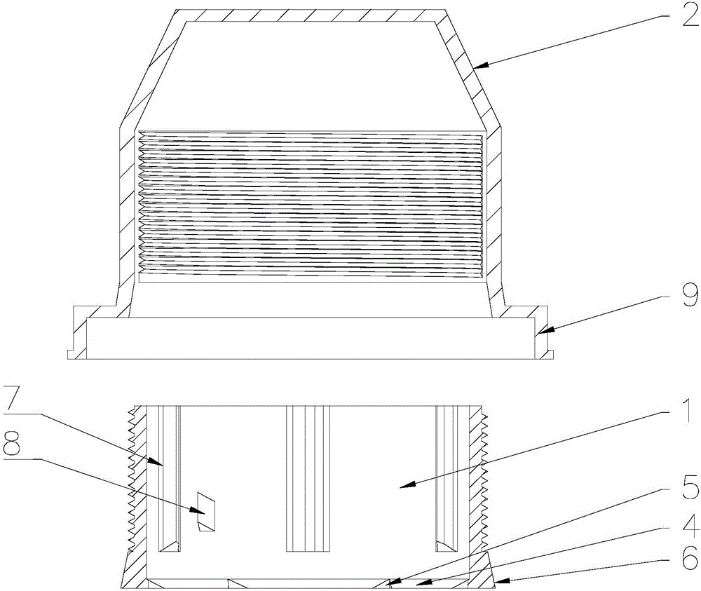
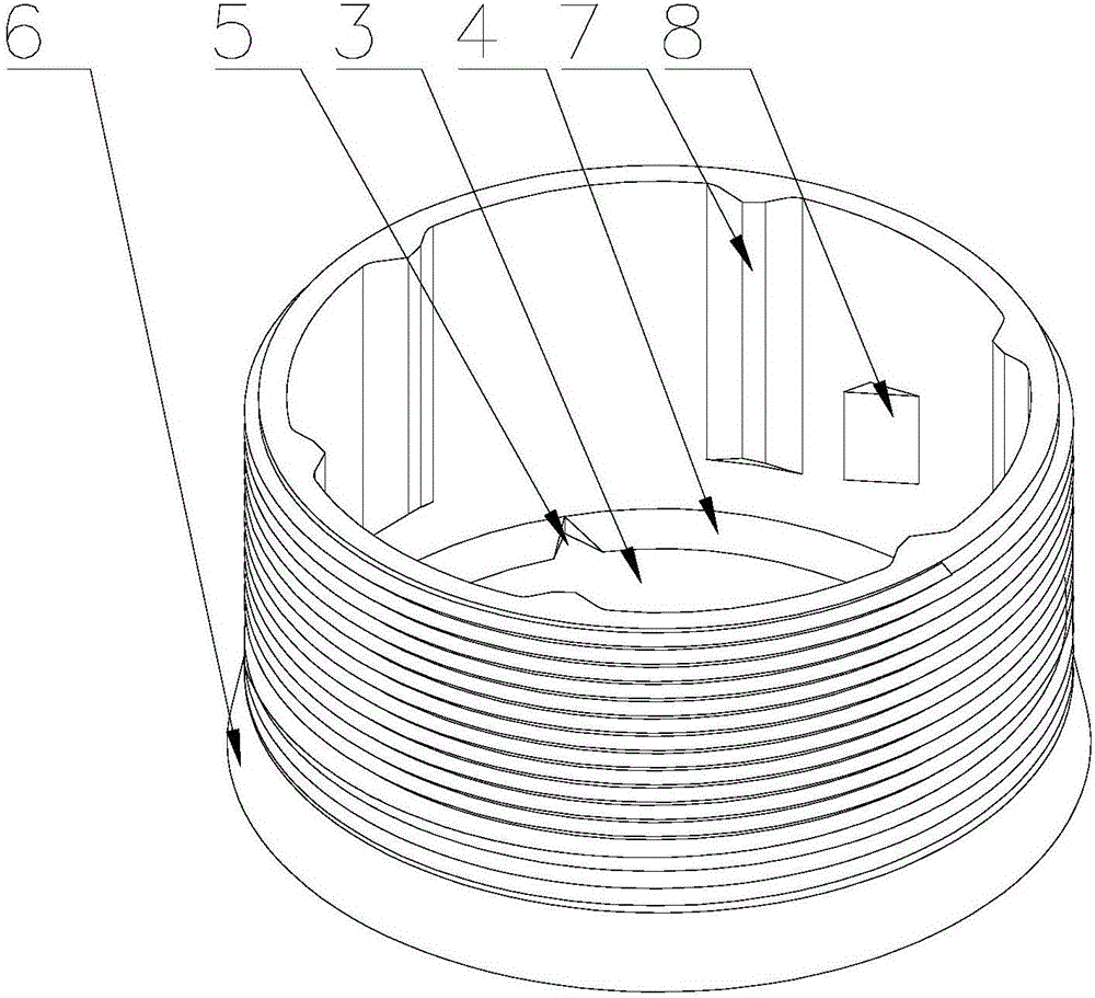
[0031] like Figure 1-Figure 3 As shown, a bolt protection cover includes a fixing part 1 and a cover body 2. The fixing part 1 has an annular inner cavity 3, and the lower edge of the annular inner cavity 3 has a plurality of tabs 4 that are convenient to be clamped at the chamfer of the nut. There is a notch 5 between the adjacent lugs 4 for the nut to enter the annular inner cavity 3 , and the cover 2 is detachably sleeved on the outside of the fixing member 1 .

[0032] In a specific embodiment, the number of lugs 4 can be determined according to the number of corners of the nut to be protected. If the nut is a square nut, the fixing part 1 has four lugs ...


PUM


Abstract

The invention relates to a bolt protection cover which comprises a fixing piece and a cover body. The fixing piece is provided with an annular inner cavity. The lower edge of the annular inner cavity is provided with a plurality of convex pieces which can be clamped to the chamfered portions of the nut conveniently. Notches allowing the nut to enter the annular inner cavity conveniently are formed between the adjacent convex pieces. The fixing piece is detachably sleeved with the cover body. According to the bolt protection cover, a fixing device is separated into the fixing piece and the cover body, the lower edge of the annular inner cavity is provided with the multiple convex pieces which can be clamped to the chamfered portions of the nut conveniently, the notches are formed between the adjacent convex pieces, the nut is sleeved with the fixing piece, corners of the nut enter the fixing piece via the notches firstly, then the convex pieces are clamped to the chamfered portions of the nut through rotating so that fixation can be achieved, the cover body and the fixing piece are fixed so as to cover the nut, protection is achieved, and the problem that protection covers are narrow in application range is solved fundamentally.

Description

technical field [0001] The invention relates to a bolt protective cover, in particular to a nut protective cover which is sleeved on the ends of nuts and bolts to prevent the nuts and bolts from being corroded. Background technique [0002] As a common connecting piece, bolts are widely used in various dynamic and static equipment, railways, bridges, shield tunnels, construction and other fields. A bolt is a fastener formed by screwing a screw and a nut through threads, and usually the end of the screw slightly protrudes from the nut. A gasket is also arranged under the nut. During use, bolts are usually exposed to the environment and are corroded by air, rain, snow and corrosive substances, which reduces the service life and may bring safety problems to production, living and transportation. At the same time, due to rust, the nut and screw rod are rusted together. , not easy to disassemble, bringing stability to maintenance and replacement. [0003] In order to prevent t...

Claims


Application Information

Patent Timeline
Patent Type & Authority Applications(China)
IPC IPC(8): F16B41/00
CPCF16B41/00
Inventor 钱福祥
Owner 钱福祥
Why Eureka
Eureka Blog
Learn More