
Nebuliser device for an inhaler apparatus and inhaler apparatus with such nebuliser device

a technology of nebuliser device and inhaler apparatus, which is applied in the direction of positive displacement liquid engine, spray nozzle, medical atomiser, etc., can solve the problems of limited mobile use suitability, comparatively voluminous and heavy, and substantially less efficient

Inactive Publication Date: 2007-06-26
DEL BON FRANCO
View PDF11 Cites 62 Cited by
  • Summary
  • Abstract
  • Description
  • Claims
  • Application Information

AI Technical Summary

Benefits of technology

[0007]The present invention shall now improve a nebuliser device of the generic type such that it meets the special conditions of a portable, in particular manually driven inhaler apparatus and that it can be used in such a device while at the same time having a sufficiently high efficacy for the use in an i

Problems solved by technology

Owing to the required compressors, power units or accumulators, these apparatuses are comparatively voluminous and heavy and are therefore only of limited suitability for mobile use.
Although inhaler apparatuses equipped with nebulisers based on ultra-sound are in general lighter and less voluminous, they are substantially less efficient.
Moreover, like the apparatuses equipped with pneumatic nebulisers they require electric energy and their mobile use is therefore relatively complicated, at least when used together with the components required for the electricity supply.
The ultrasonic influence may furthermore also destroy the medicinal drug.
For the intermittent operation of a portable inhaler apparatus which in practice often lasts only for a few breaths, the nebuliser device designed for stationary continuous operation is at best of limited suitability also because of the limitation of the operating position.

Method used


Image

  • Nebuliser device for an inhaler apparatus and inhaler apparatus with such nebuliser device
  • Nebuliser device for an inhaler apparatus and inhaler apparatus with such nebuliser device
  • Nebuliser device for an inhaler apparatus and inhaler apparatus with such nebuliser device

Examples


Embodiment Construction

[0010]The following drawings illustrate exemplary embodiments of the invention in more detail. They show:

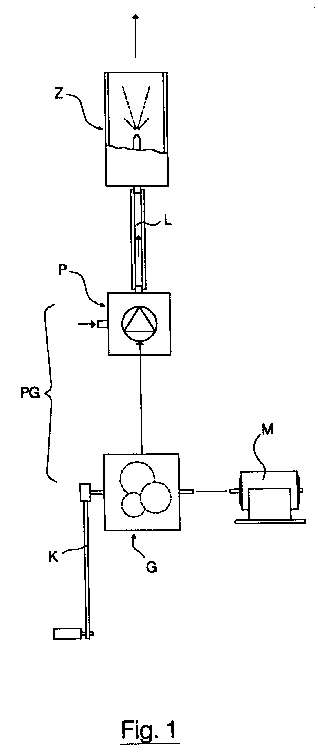
[0011]FIG. 1 shows a schematic drawing of an exemplary inhaler apparatus in which the nebuliser device of this invention can be used,

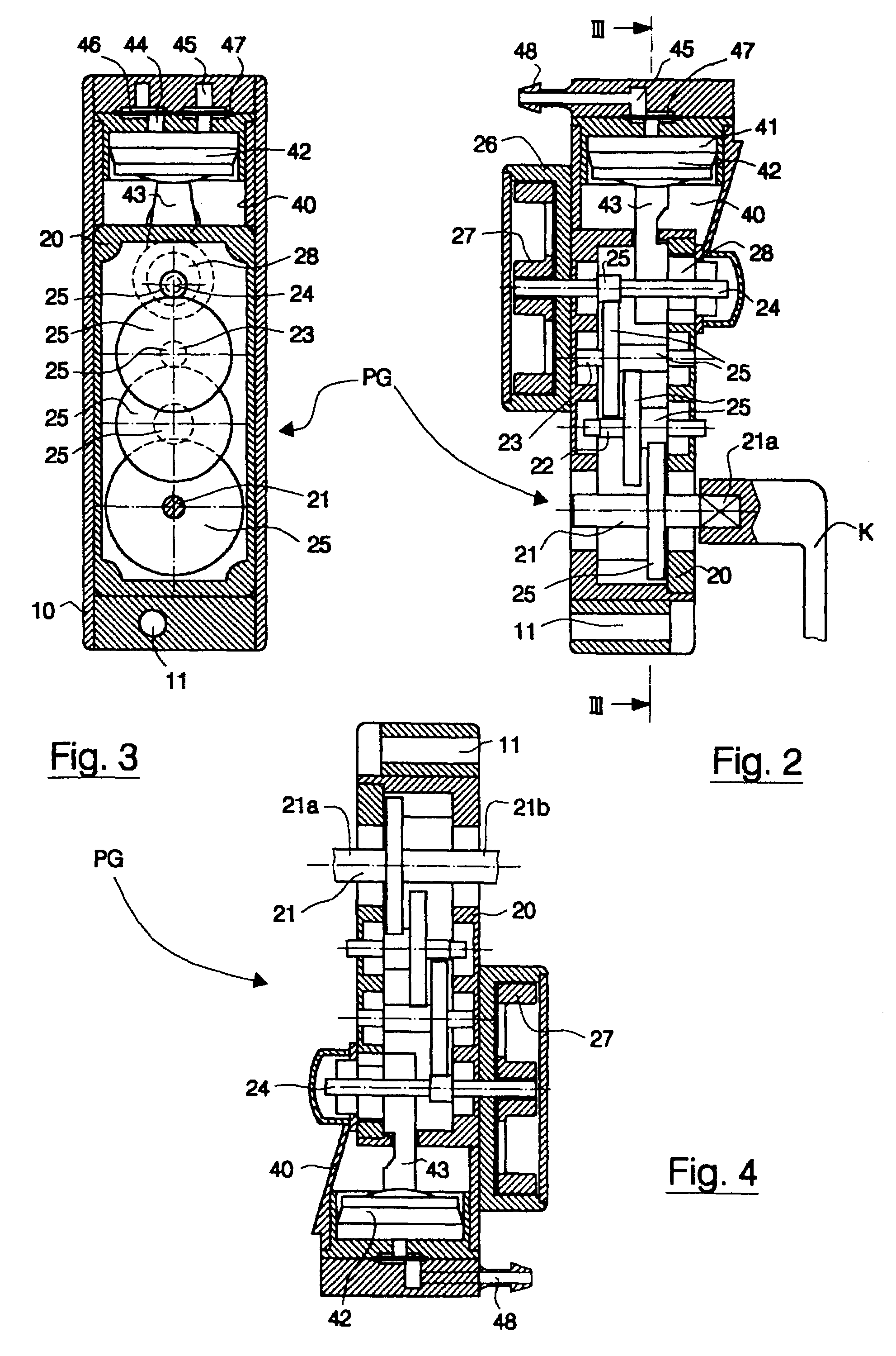
[0012]FIG. 2 shows a longitudinal section through the pump and gear unit of a first concrete embodiment of the inventive inhaler apparatus,

[0013]FIG. 3 shows a section along the line III—III of FIG. 2,

[0014]FIG. 4 shows a section in analogy to FIG. 2, but in a representation rotated through 180°, through a variant of the pump and gear unit,

[0015]FIGS. 5–8 show slightly simplified views of four embodiments of an inhaler apparatus equipped with a pump and gear unit in accordance with FIGS. 2 and 3,

[0016]FIG. 9 shows a slightly simplified view of a further exemplary embodiment of an inhaler apparatus equipped with a pump and gear unit in accordance with FIG. 4,

[0017]FIG. 10 shows a view of a further embodiment of an inhaler apparatus equipped with a mo...


PUM


Abstract

An inhaler device having a pump unit (P) for producing a stream of compressed air, a drive (G) for the pump unit and a nebuliser unit (Z) which communicates with the pump unit and which is driven pneumatically. The inhaler device produces and releases an air stream which is charged in controlled manner with fine liquid active ingredient particles. The pump unit (P) is equipped with a short-stroke piston pump. The drive takes the form of a crank gear (G) having a gear transmission which can be driven by means of a hand crank (K), the output shaft of which is kinematically connected to the pump piston via an eccentric and drives the pump piston. The inhaler device need not use any elaborate energy supply and can be built in compact and handy fashion. It can be ready for use anytime and anywhere and is therefore particularly suitable for mobile use.

Description

RELATED APPLICATIONS[0001]This application claims priority under 35 U.S.C. §119 to Swiss Application 1828 / 00 filed in Switzerland on 20 Sep. 2000 and to Swiss Application 0849 / 01 filed in Switzerland on 10 May 2001, and under 35 U.S.C. §120 to PCT / CH01 / 00515 filed as an International Application on 23 Aug. 2001, the entire contents of which are hereby incorporated by reference.BACKGROUND[0002]The present invention relates to a nebuliser device intended for an inhaler. The invention also relates to an inhaler apparatus equipped with such a nebuliser device.[0003]Bronchial therapy normally uses inhaler apparatuses which permit the fine dispersion of a liquid or powdered active ingredient formulation and its controlled release into an air stream which is inhaled by the patient. To achieve optimum efficacy it is important that as large as possible a part of the particles (droplets) produced in this manner has a maximum size of 5μ.[0004]Classic inhaler apparatuses more or less meeting th...

Claims


Application Information

Patent Timeline
IPC IPC(8): A61M11/00F04B33/00A61M11/02A61M11/06A61M15/00A61M16/00B05B1/34F04B33/02F04B35/01
CPCA61M11/06F04B33/02A61M11/002A61M16/0063A61M16/107
Inventor DEL BON, FRANCO
Owner DEL BON FRANCO
Learn More