
Superconducting wire transposition method and superconducting transformer using the same

a superconducting transformer and wire transposition technology, applied in the direction of superconducting magnets/coils, magnets, magnetic bodies, etc., can solve the problems of increasing winding loss, imposing several superconducting transformers, and causing voltage difference between internal wires and external wires of windings

Inactive Publication Date: 2007-06-05
HYOSUNG CORP
View PDF6 Cites 44 Cited by
  • Summary
  • Abstract
  • Description
  • Claims
  • Application Information

AI Technical Summary

Benefits of technology

The present invention provides a method for transposing superconducting wires without losing their superconductivity. This is achieved by starting the winding of the transformer at different positions on the disk and using different superconducting wires for the connection between the disks. The method can be applied to various superconducting devices such as electric motors, magnetic energy storage, and fault current limiters.

Problems solved by technology

In addition, an induced voltage difference occurs between the internal wire and the external wire of the winding because of the difference in the number of opposite flux.
As a result thereof, a circulating current flows between the parallel conductors, and this in turn increases in the winding loss.
Unfortunately however, the superconducting transformer imposes several problems with the occurrence of the above-described transposition.
When this occurs, superconductivity is lost, and severe damages can be done on the superconducting winding.
However, a different approach has to be made to apply the transposition method to superconductors because superconductors are made out of ceramic materials and easily lose their superconductivity when they are bent or twisted under pressure.
Thus, the traditional transposition method used in the copper winding is not equally effective for the superconductors.

Method used


Image

  • Superconducting wire transposition method and superconducting transformer using the same
  • Superconducting wire transposition method and superconducting transformer using the same
  • Superconducting wire transposition method and superconducting transformer using the same

Examples


Embodiment Construction

[0031]A preferred embodiment of the present invention will be described herein below with reference to the accompanying drawings.

[0032]Transposition in parallel conductors will be first described with reference to FIG. 3.

[0033]Referring to a bobbin structure shown in FIG. 3, wings 32 are formed on both sides centering around a base 30, and a spacer 34 is disposed at the central upper portion of the base 30. And, disks 36 are formed in areas between the wings 32 and the spacer 34, respectively. The disk 36 is formed of superconducting wires 38.

[0034]Each disk 36 in FIG. 3 has a successive winding structure, and the two disks are modularized to one, forming a double disk 36 together. As described above, the bobbin structure features supporting the double disk 36.

[0035]For instance, if the total number of turns of 4 superconducting wire strands connected in parallel is “80”, transpositions should occur at least three times, and four double disks should be formed. In other words, the nu...


PUM

PropertyMeasurementUnit
angleaaaaaaaaaa
superconductingaaaaaaaaaa
superconductiveaaaaaaaaaa

Abstract

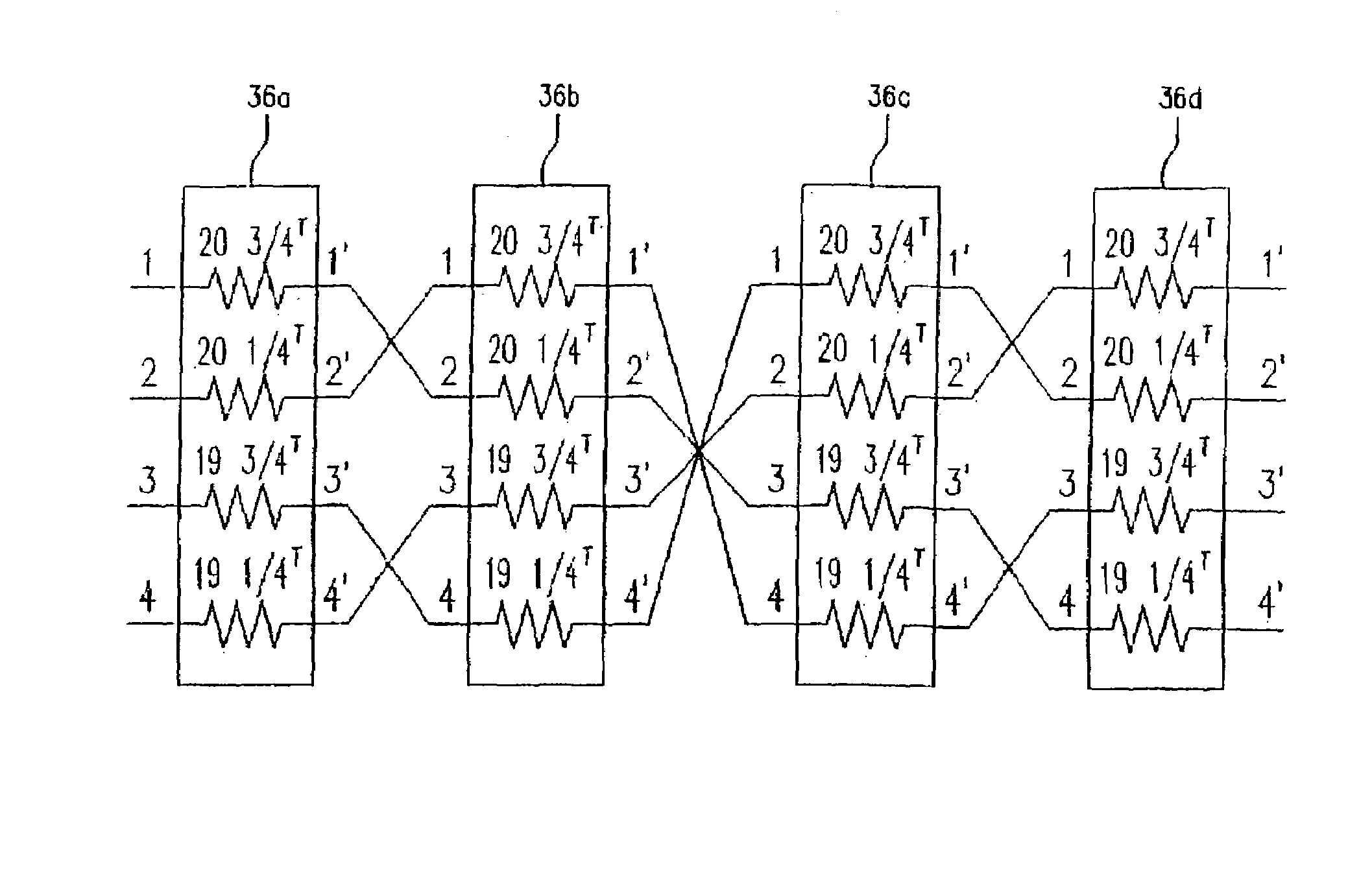
The present invention discloses a superconducting wire transposition method and superconducting transformer whose winding is formed of superconducting wire to enable the formation of transpositions. The superconducting wire transposition method characterized of different winding start positions of at least two disks wound with a plurality of parallel superconductive wires, and usage of different superconducting wires for conductors to be connected between the disks, thereby forming transpositions outside of the disks. Preferably, part of the plurality of disks are rotatably assembled in pairs so as to form transpositions while maintaining a total number of windings equally. Therefore, according to the present invention, transpositions can be formed without bending or welding superconducting wires and thus, deteriorations in superconductivity can be prevented.

Description

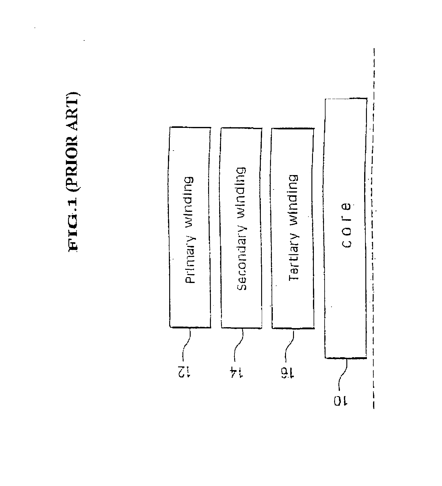
BACKGROUND OF THE INVENTION[0001]1. Field of the Invention[0002]The present invention relates in general to a superconducting wire transposition method, more specifically, to a superconducting wire transposition method and superconducting transformer whose winding is formed of superconducting wire to enable the formation of transpositions.[0003]2. Description of the Related Art[0004]In general, a transformer is a passive electrical device used to transfer an alternating current (or voltage) that is supplied to one winding to another winding by means of electromagnetic induction. The simplest type of transformer consists of at least two electric circuits and one common magnetic circuit for the electromagnetic induction. The electric circuits are formed with windings, and the magnetic circuit is formed of a steel core and arranged so that the magnetic circuit is in opposition to the electric circuit.[0005]As shown in FIG. 1, the transformer includes a core 10, and a plurality of windi...

Claims


Application Information

Patent Timeline
Patent Type & Authority Patents(United States)
IPC IPC(8): H01F6/00
CPCH01F6/06H01F36/00H01F2027/2838Y02E40/66Y10S336/01Y02E40/60H01F27/30
Inventor SONG, HEE SUCKHEO, WOO HENGPARK, JUNG HOCHOI, KYEONG DALKIM, WOO SEOKKIM, SUNG HOON
Owner HYOSUNG CORP
Learn More