
Method for testing the thermally induced unbalance of a rotating machine part, in particular the rotor of a turbogenerator, and device for carrying out the method

a technology of rotating machine parts and thermally induced unbalance, which is applied in the direction of dynamo-electric machines, instruments, structural/machine measurement, etc., can solve the problems of thermal unbalance, disproportionate long-term use of methods, and a considerable outlay in the setup of test stands, so as to reduce the outlay

Inactive Publication Date: 2007-06-05
GENERAL ELECTRIC TECH GMBH
View PDF6 Cites 0 Cited by
  • Summary
  • Abstract
  • Description
  • Claims
  • Application Information

AI Technical Summary

Benefits of technology

The present invention provides a method for testing the thermally induced unbalance of a rotating machine part, particularly the rotor of a turbogenerator, which avoids the disadvantages of previous methods. The method involves heating the part to a higher temperature and measuring the resulting temperature variations using a closed heating cell. The cooling medium flows through the part and interacts with it, resulting in a higher temperature. The method is faster and more accurate than previous methods, and a device for carrying out the method is also provided. The technical effects of the invention include improved accuracy and efficiency in testing for thermally induced unbalance, as well as reduced costs and improved test conditions.

Problems solved by technology

This test method, admittedly, is very close to the mechanisms which give rise to thermal unbalance during subsequent operation.
However, it requires a considerable outlay in terms of the set-up of the test stand: electromagnetic shields, cooling, an exciting system, sufficient drive power and suitable measuring and monitoring systems.
This method may last through a disproportionately long time during which both the rotor body and the winding heat up.
As a result, some important mechanisms of the rotor unbalance are not reproduced, and experience has shown that this leads to disadvantages in terms of the evidential force of such tests.

Method used


Image

  • Method for testing the thermally induced unbalance of a rotating machine part, in particular the rotor of a turbogenerator, and device for carrying out the method
  • Method for testing the thermally induced unbalance of a rotating machine part, in particular the rotor of a turbogenerator, and device for carrying out the method
  • Method for testing the thermally induced unbalance of a rotating machine part, in particular the rotor of a turbogenerator, and device for carrying out the method

Examples


Embodiment Construction

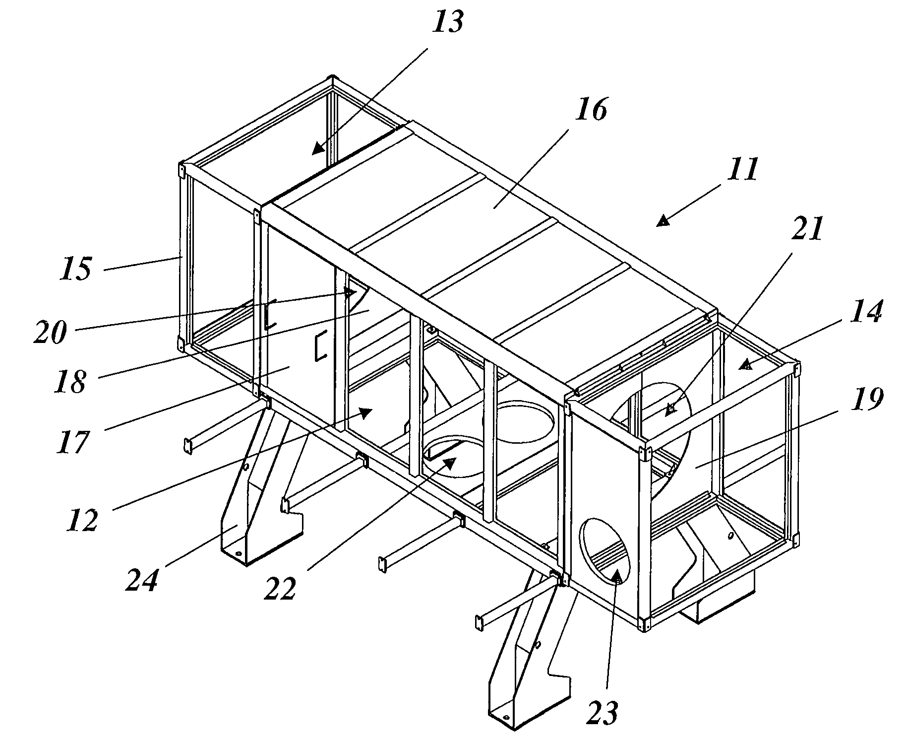
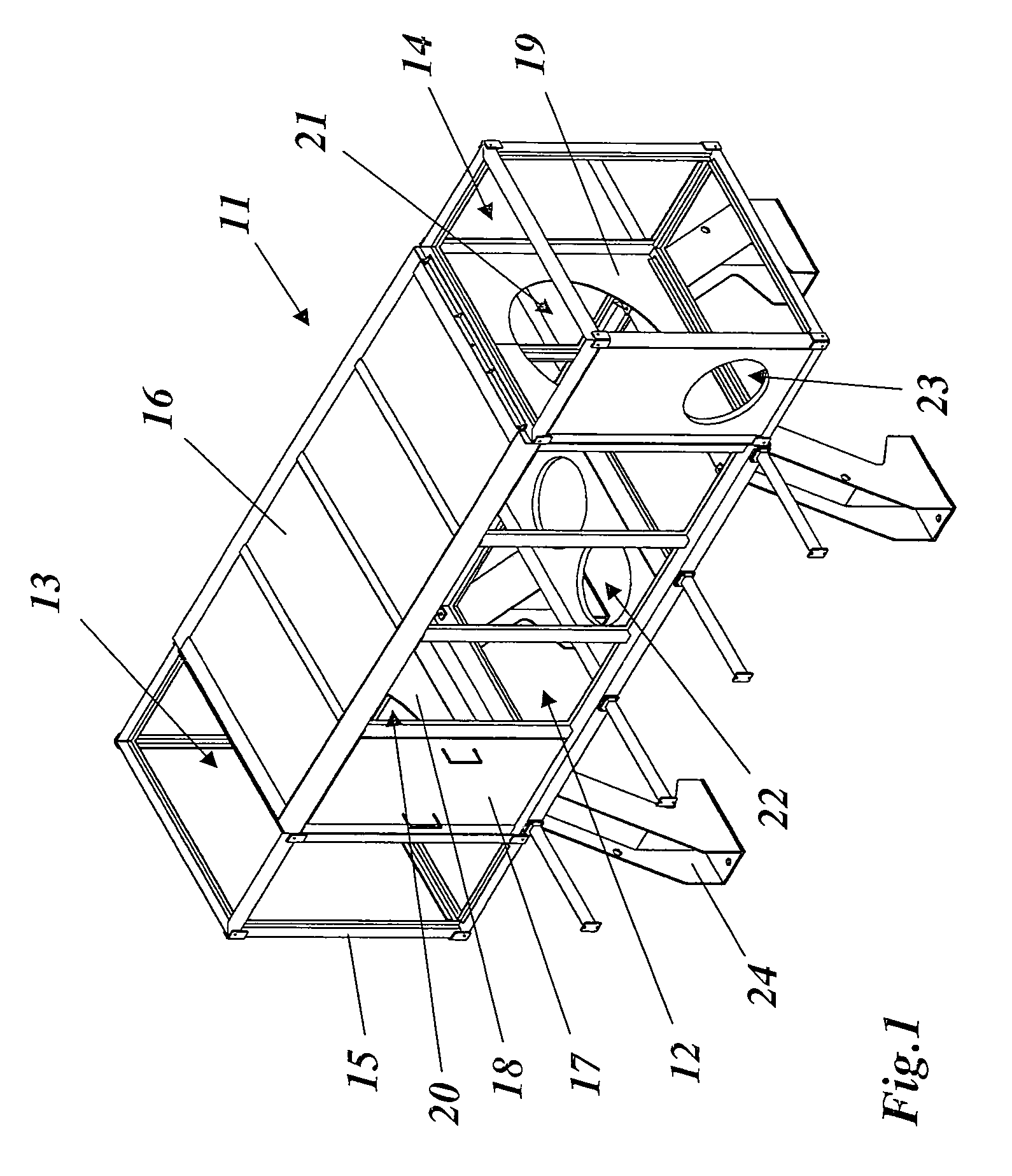
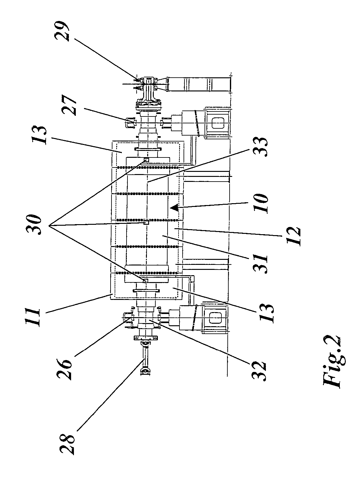
[0031]FIG. 4 reproduces a highly diagrammatic part view of an arrangement for testing for thermally induced unbalance of the rotor of a turbogenerator. Only the left half of the rotor 10, which is constructed essentially symmetrically with respect to a midplane 45, is illustrated. The rotor 10 rotatable about a rotor axis 33 has a continuous rotor shaft 32 and a rotor barrel 31 which is formed in the middle of the rotor shaft 32 and in which the rotor winding 34 is laid in axially running grooves and is secured against the effects of centrifugal forces by means of wedges 35 or by comparable means. According to FIGS. 3 and 4, a cooling medium (air or another gas) flows through the rotor barrel 31 or the rotor winding 34, enters in the axial direction in the usual way on the end faces of the rotor barrel 31 and emerges again in the radial direction on the circumference of the rotor barrel 31 (see the flow arrows in FIGS. 3 and 4). According to FIG. 3, cooling may take place radially i...


PUM


Abstract

In a method for testing the thermally induced unbalance of a rotating machine part, in particular the rotor of a turbogenerator, the rotating machine part or the rotor balanced at normal temperature is brought in the demounted state first to nominal rotational speed and held at this, while its temperature is varied and, at the same time, the transient variations in oscillations of the rotating machine part or rotor which are caused are measured. During the test, the rotating machine part or the rotor is surrounded at least partially by a closed heating cell, a cooling medium flows around and / or flows through the rotating machine part or the rotor in the heating cell, and the heating of the rotating machine part or of the rotor takes place essentially due to the flow-dynamic losses arising from the interaction of the rotating machine part or of the rotor with the circulating cooling medium.

Description

[0001]Priority is claimed to Swiss Patent Application No. CH 00669 / 05, filed on Apr. 13, 2005, the entire disclosure of which is incorporated by reference herein.[0002]The present invention relates to the field of rotating machines. It refers to a method for testing the thermally induced distortion or unbalance of a rotating machine part, according to the preamble of claim 1. It refers, furthermore, to a device for carrying out the method.BACKGROUND[0003]Rotors of large turbogenerators, before being built into the stator, are normally subjected at the manufacturer's to a test, referred to as “warm-up”, which follows the balancing of the rotor in the cold state in the centrifuge. The “warm-up” is intended to simulate the thermally induced unbalances of the rotor which occur during the normal operation of the ready-assembled machine, so that a deviating oscillation behavior can be detected at an early stage and corrected even during production.[0004]A thermally induced warping of the ...

Claims


Application Information

Patent Timeline
Patent Type & Authority Patents(United States)
IPC IPC(8): G01M1/16
CPCG01M1/02G01M1/16G01M99/002H02K15/165
Inventor AUBRIAT, ERIC JEANBREGY, LUDOVICHOLMES, ANDREW JOHNKLEIN, GEORG STEPHANVEITH, ERICVERRIER, MICHEL CLAUDE
Owner GENERAL ELECTRIC TECH GMBH
Learn More