Wedge for use in dental restoration

Active Publication Date: 2007-05-29
GARRISON TOM +1
View PDF16 Cites 10 Cited by
  • Summary
  • Abstract
  • Description
  • Claims
  • Application Information

AI Technical Summary

Benefits of technology

[0008]According to the present invention, a wedge for use in dental restoration is provided that reduces trauma to the gum tissue when inserted between adjacent teeth and, further, minimizes, if not eliminates, degradation of the surface of the restoration when removed.
[0009]In one form of the invention, a dental wedge includes an elongate body with a lower surface, a pair of spaced apart sides that extend from the lower surface, and a distal end. The body includes rounded corners at the juncture between the sides and the lower surface, and the distal end is also rounded such that the wedge does not present any sharp points or edges to the tissue when being inserted into the interproximal area between adjacent teeth to minimize trauma to the surrounding tissue.
[0010]Furthermore, the sides and the lower surface are concave to form a contoured body that provides increased contact between the wedge and the teeth and gum to increase friction between the wedge and the gum and teeth, which holds the wedge more securely in place and, further, provides more contoured contacts for the restoration. In one aspect, the corners at the juncture of the sides and the lower surface are radiused in a range of 0.003 inches to 0.050. In addition, the radii of the corners may vary across their respective lengths or may be generally uniform across their lengths.

Problems solved by technology

If a decayed portion of a tooth is located near its interproximal area, the tooth structure itself is usually insufficient to provide support to the filling material during the filling process.
Most commercially available wedges are tetrahedral in shape and tend to have relatively sharp edges, which can induce trauma to the gum tissue.
When a dentist places a wedge in the interproximal space, which has an abrupt cross-sectional change, there is a likelihood that the wedge will back out.
However, it has been found in some instances that these protuberances may leave the restored surface with an irregular surface, which may cause accumulation of plaque or food and, thus, lead to decay and periodontal problems.
In addition, the inserted distal end of a conventional wedge, which is pointed, can further induce damage to the gum tissue.
This could result in the patient experiencing some discomfort, and could inhibit the dentist from performing a proper restoration.

Method used


Image

  • Wedge for use in dental restoration
  • Wedge for use in dental restoration
  • Wedge for use in dental restoration

Examples


Embodiment Construction

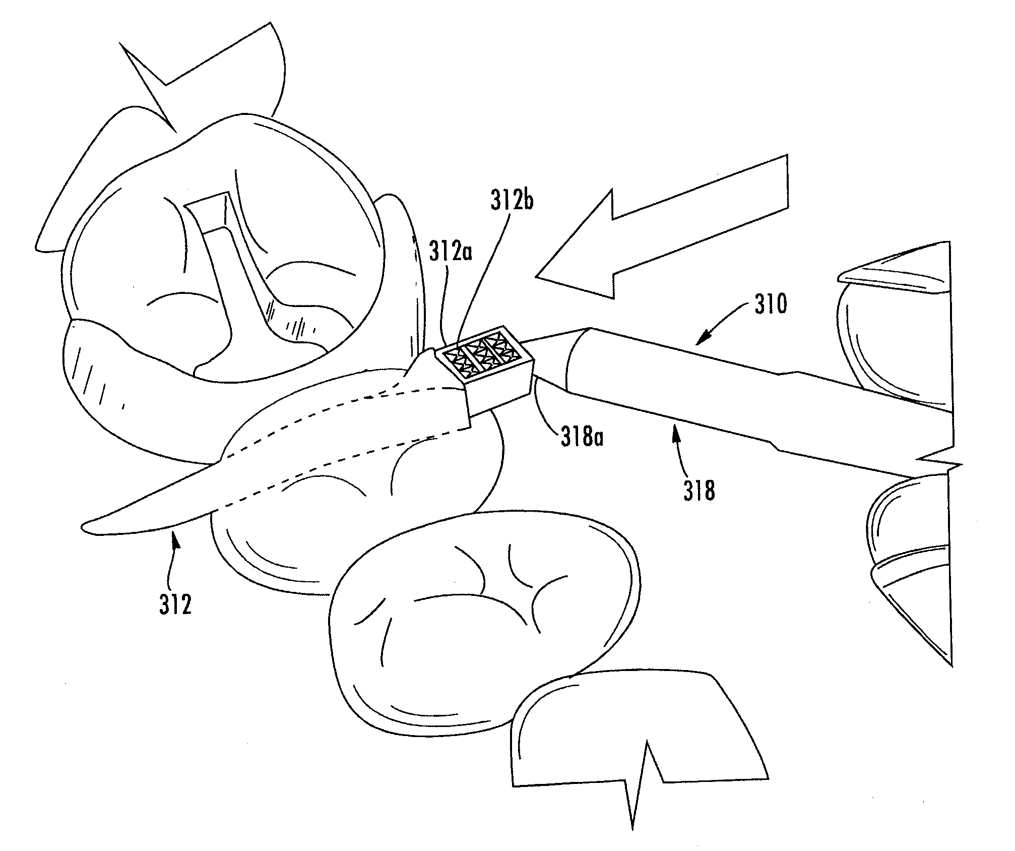
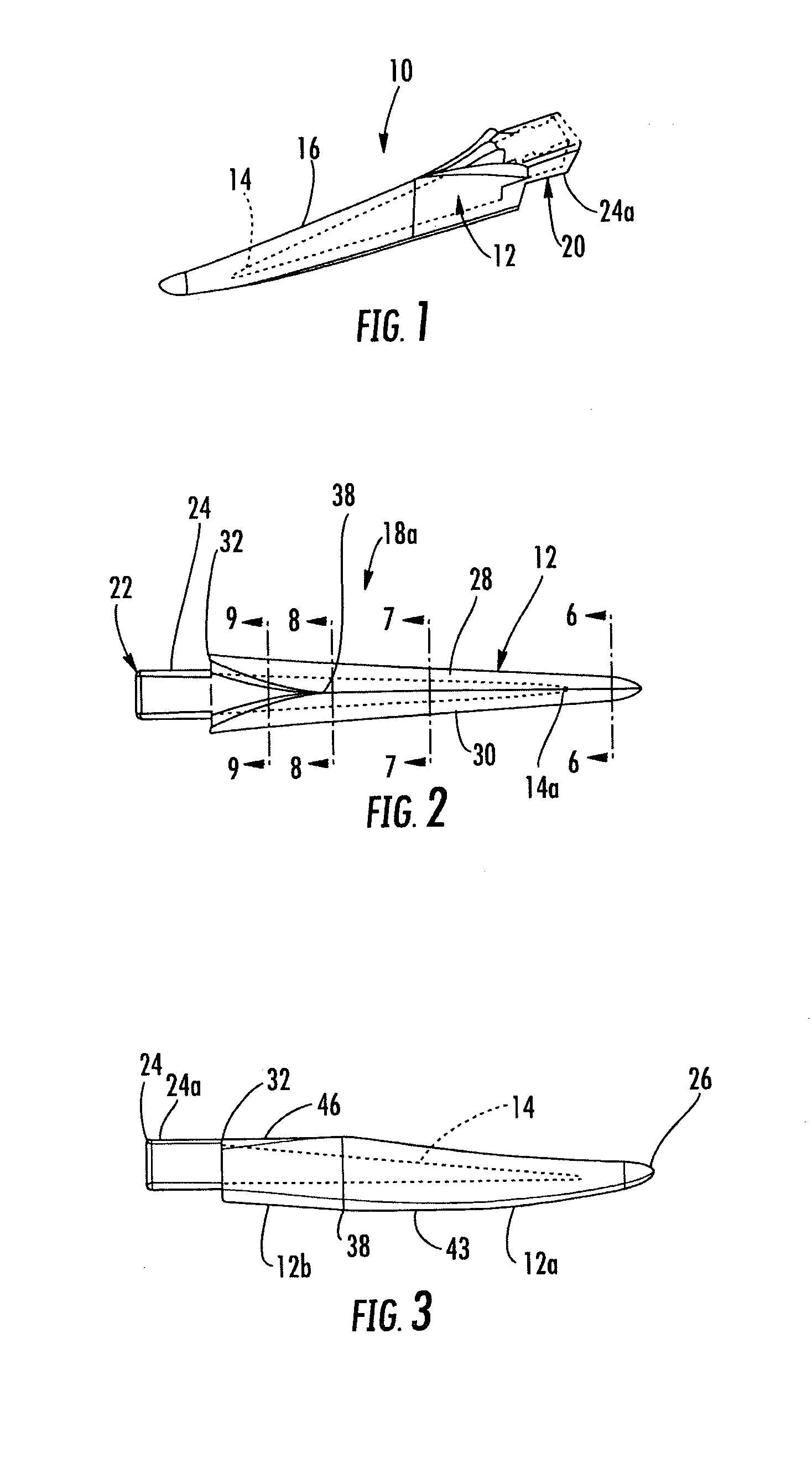
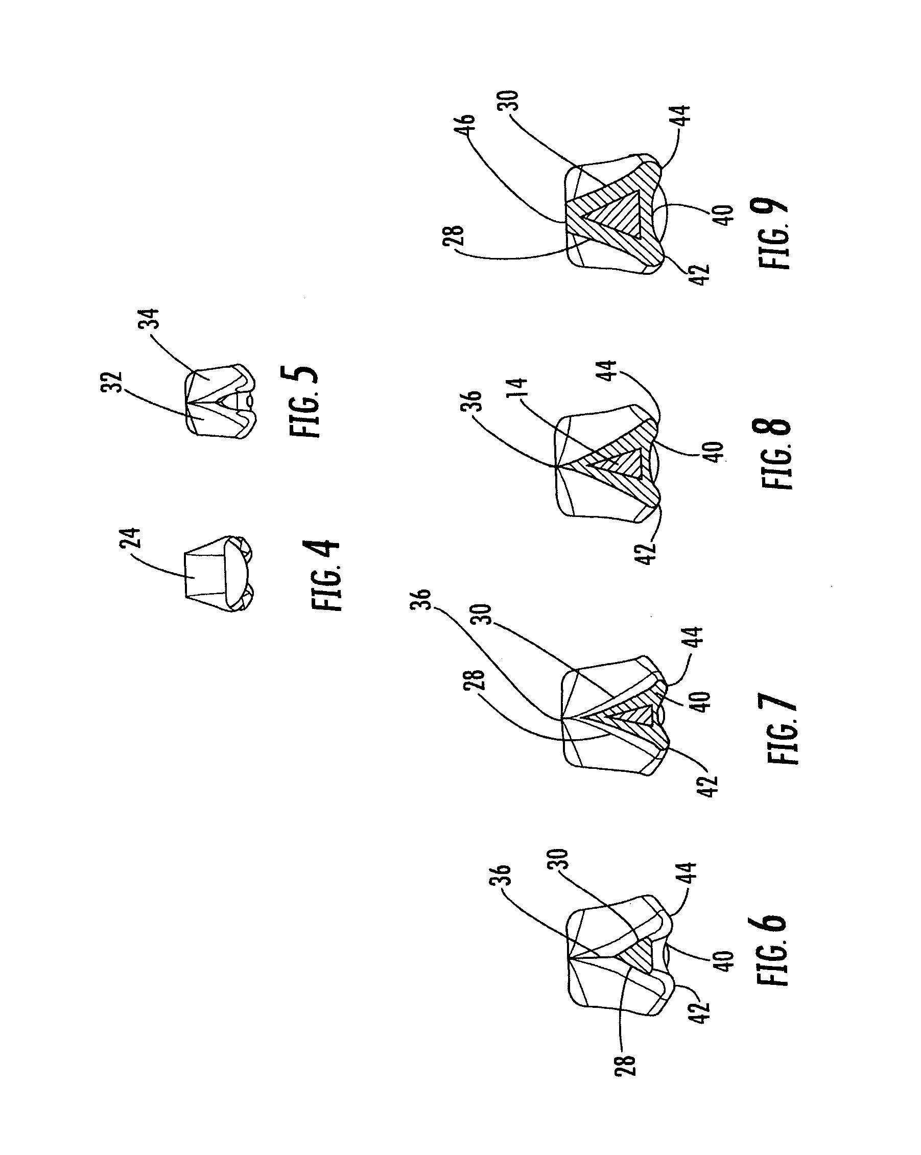
[0096]Referring to FIGS. 1–9, the numeral 10 generally designates a dental wedge of the present invention. As will be more fully described below, dental wedge 10 minimizes the trauma to the gum tissue when the dental wedge is inserted between teeth (as will be more fully discussed in reference to FIGS. 34 and 35) while providing a wedge that exhibits reduced slippage after insertion between the adjacent teeth.

[0097]As best seen in FIGS. 1–3, dental wedge 10 includes an elongate body 12 that includes a core 14 and an outer surface 16. Preferably, outer surface 16 is softer than core 14 to minimize trauma to the gum tissue when wedge 10 is inserted in the interproximal area between adjacent teeth. For example, core 14 may comprise a plastic material, a metal or wood or other suitable generally rigid materials. In contrast, outer surface 16 is preferably formed from a softer plastic material, such as an elastomer, including a thermal plastic elastomer (TPE), such as SANTOPRENE®, having...


PUM


Abstract

A dental wedge comprises an elongated body, which includes a distal end and a proximal end which tapers to the distal end. The distal end defines an insertion end and tilts upwardly. The elongate body has a first portion starting at the distal end and has a second portion that ends at the proximal end. The first portion has a generally triangular-shaped cross-section and the second portion has a generally trapezoidal cross-section.

Description

[0001]This application claims priority from pending U.S. provisional Pat. application entitled WEDGE FOR USE IN DENTAL RESTORATION, Ser. No. 60 / 392,209, filed Jun. 28, 2002, which is incorporated by reference in its entirety.TECHNICAL FIELD AND BACKGROUND OF THE INVENTION[0002]The present invention relates to a wedge and, more particularly, to a dental wedge used in dental restoration.[0003]If a decayed portion of a tooth is located near its interproximal area, the tooth structure itself is usually insufficient to provide support to the filling material during the filling process. In order to retain the filling material in an excavated cavity, while the filling material hardens, a band is typically positioned about the tooth and secured tightly about the tooth so that the band forms an outer shell or matrix. In addition, it is often necessary to separate the adjacent teeth so that the filling material when hardened will provide adequate contact between the teeth to restore the teeth...

Claims


Application Information

Patent Timeline
IPC IPC(8): A61C7/00A61C5/12
CPCA61C5/127A61C5/88
Inventor GARRISON, TOMANDERSON, ROBERT
Owner GARRISON TOM
Why Eureka
Try Eureka