
Floatdown implement for small vehicles

Inactive Publication Date: 2007-05-22
BAKER ROBERT E
View PDF16 Cites 22 Cited by
  • Summary
  • Abstract
  • Description
  • Claims
  • Application Information

AI Technical Summary

Benefits of technology

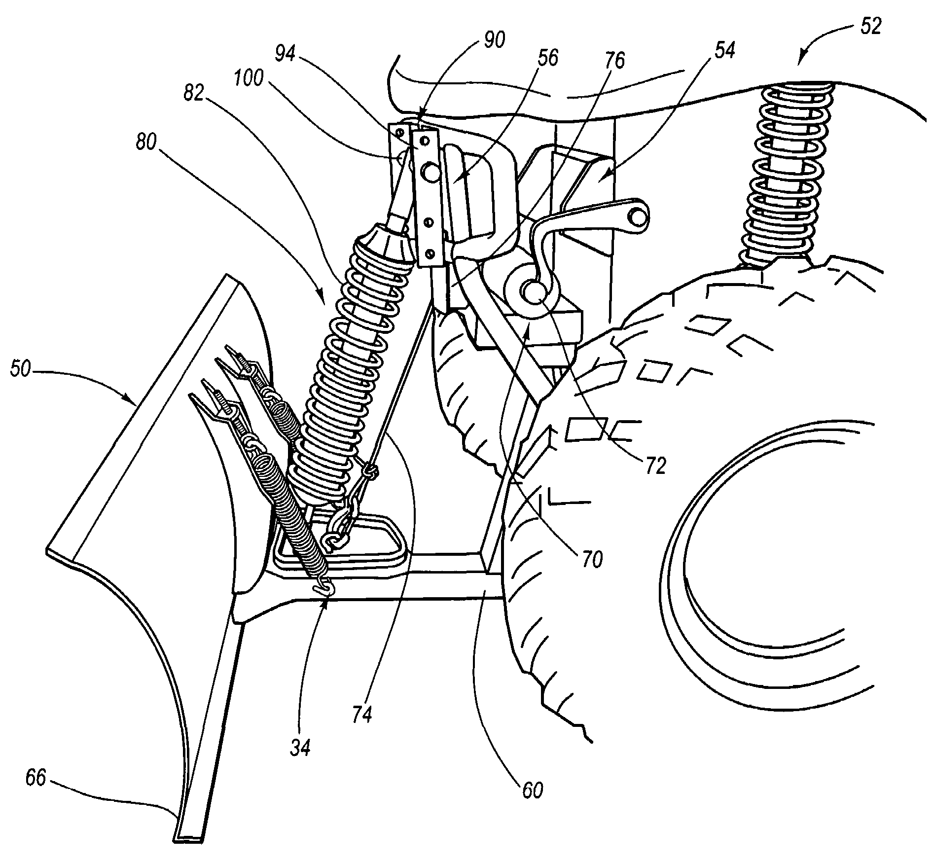
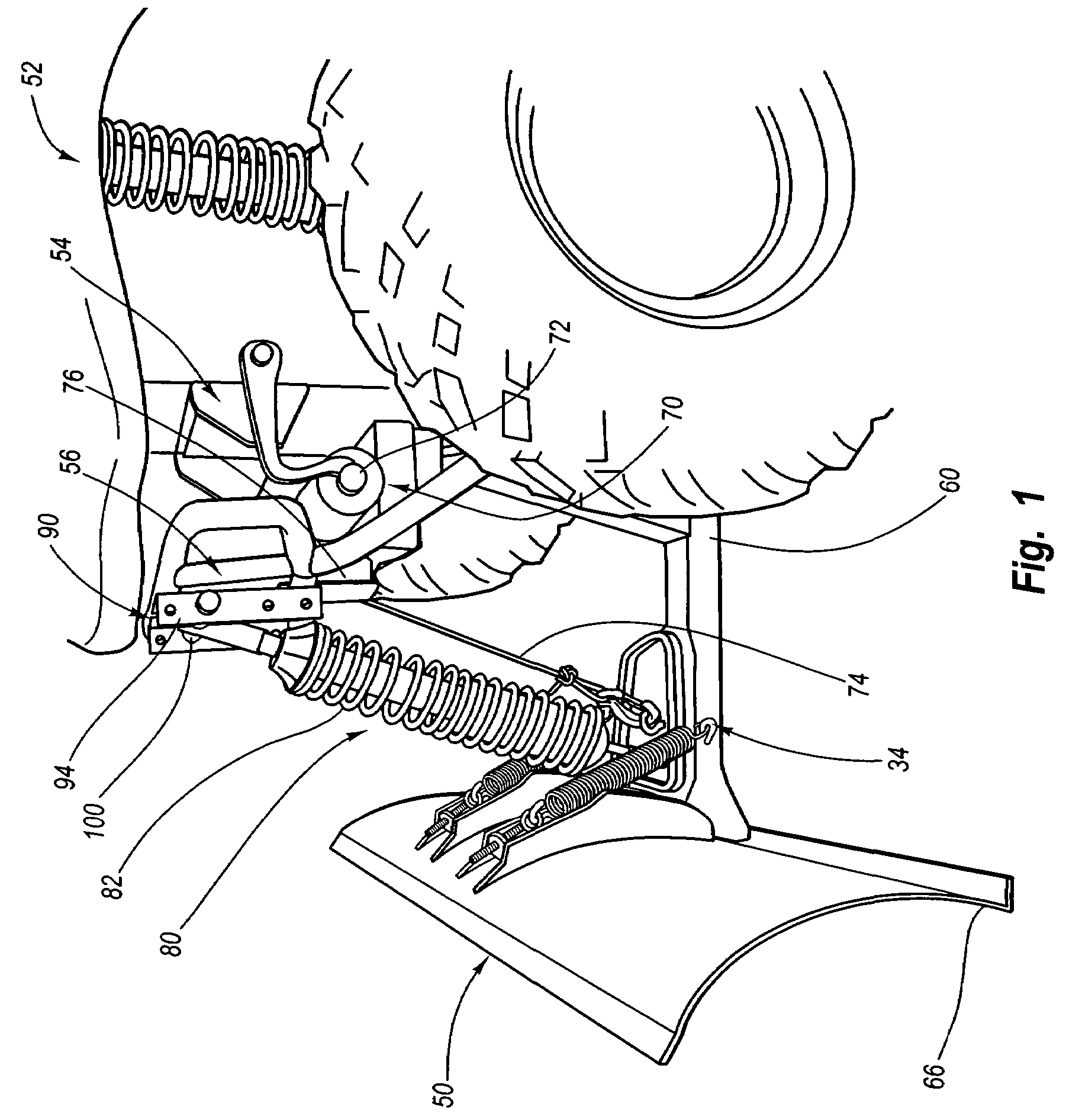
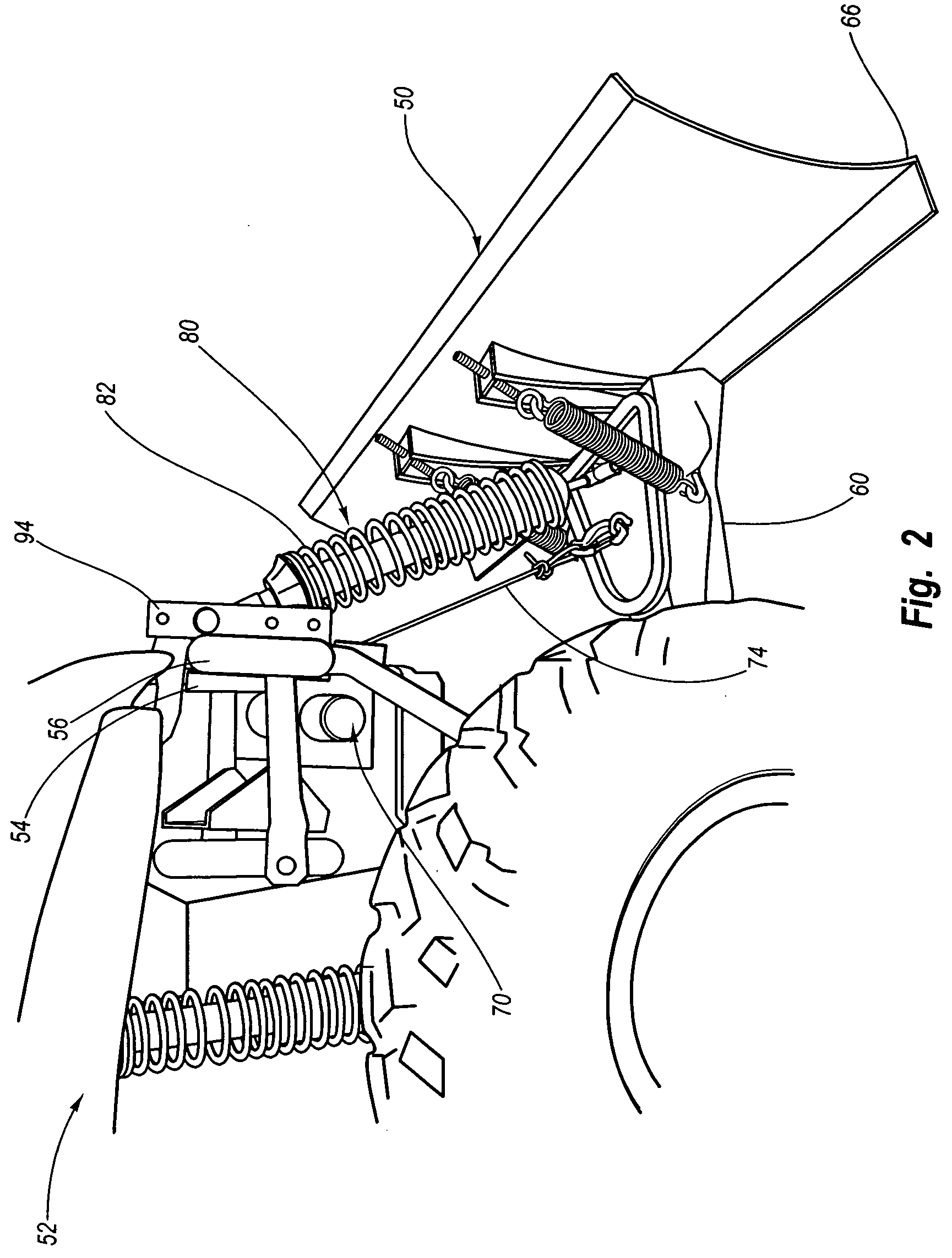
[0015]The present invention comprises a floatdown implement capable of being mounted to and supported by a small vehicle, such as an all terrain vehicle (“ATV”), garden tractor, small farm tractor or small pickup truck. A floatdown implement in accordance with the present invention maximizes the implement's ground surfacing capabilities by incorporating a floatdown member to apply a substantially downward force to the implement while, in some embodiments, lifting weight from the end of the vehicle to which it is mounted.
[0016]Specifically, in selected embodiments, a floatdown implement in accordance with the present invention may comprise a spring loaded shock absorber having a dampening element. One end of the shock absorber may be attached to the vehicle while an opposite end is attached to the implement. The shock absorber functions to provide a continuous adjustable downward force to the implement to improve responsiveness to surface characteristics, thereby promoting efficient surface treatment.

Problems solved by technology

As a result, such vehicles are frequently used in connection with farm work, landscaping, and other such labor-intensive activities.
A removable snow plow, for example, may be mounted to a small vehicle to remove snow and ice from various surfaces, such as driveways, sidewalks, short road segments, parking lots, and other similar relatively limited areas of space that are too small for a full size snow plow to maneuver, yet large enough that shoveling by hand would result in a very labor intensive and time consuming task.
First, small vehicles such as ATVs are typically quite maneuverable.
Fourth, there is virtually no physical exertion or energy expended by the operator of a small vehicle, as opposed to a significant amount where shoveling by hand.
Due in part to the space occupied underneath the vehicle by the plow frame, however, and also due to the cant of the plow blade, the plow blade cannot typically be raised more than 2 or 3 inches off of the ground.
Moreover, many prior art plow designs suffer from the following deficiencies.
First, many plow users lack the strength or energy required to manipulate the plow blade in a manually operated system.
Second, prior art plow systems are generally difficult to mount and remove from a vehicle.
With the plow installed, the vehicle is virtually useless for any other purpose.
Indeed, as discussed above, there is very little clearance under the bottom cutting edge of the plow blade even when the blade is completely lifted.
There is also very little clearance under the chassis of the vehicle due to the presence of the mounting frame beneath the chassis.
Further, the weight of the plow substantially alters the maneuverability of the vehicle to which it is attached.
Another drawback to prior art systems is that many small vehicles, especially ATVs, are relatively light in weight (e.g., lighter ATVs range from about 450 lbs. to 600 lbs. in total weight not including the weight of the plow).
Such vehicles thus tend to be underpowered or lack sufficient traction to move large quantities of snow.
Another problem associated with prior art plow designs is blade floating, which results in irregular and / or uneven ground surfacing.
Also, blade floating leaves behind residual snow and ice deposits, which may build up and create slush and other problems once warmer weather arrives.
Adding weight to the blade of the plow helps reduce floating, but requires the vehicle to work harder and lose critical traction.
When the blade is forced down under added weight, the vehicle has a much more difficult time pushing the blade and gripping the surface, effectively negating any efficiency in blade leveling that may otherwise have been gained.
During the period the blade is pivoted, however, the bottom edge of the plow loses contact with the ground, thus forming a residual ridge of snow and ice.
A secondary effect of such a ridge is that as the tires of the vehicle cross the ridge, the vehicle is lifted up over the ridge, often causing the plow to temporarily leave the ground.
Once the object is cleared, the spring causes the blade to abruptly snap back into position, thus contributing to further leveling and / or floating problems.
Another disadvantage to traditional plow systems, particularly to V-plow systems where a pair of plow blades is connected along a vertical hinge, is that it is difficult to maintain the bottom cutting edge of the plow blade flush with the ground surface unless the plow is precisely mounted on the vehicle and the plow blades are accurately positioned to align the bottom cutting edge flush with the ground.
In addition, it is difficult or even impossible to provide evenly distributed downward pressure to a V-blade plow as the bottom cutting edge of the V-plow does not in general remain flush with the ground surface when rotated downward.
Although an operator-controlled actuator mechanism that provides power to an electric actuator to raise and lower the plow may overcome some of these deficiencies, prior art designs that incorporate such a mechanism nevertheless suffer from certain inherent problems.
Namely, electrically powered plow designs in the prior art tend to add a significant amount of weight to the plow as a result of requiring a proprietary motor.
Also, the incorporation of such a motor renders the plow much more expensive than a manually operated plow.

Method used


Image

  • Floatdown implement for small vehicles
  • Floatdown implement for small vehicles
  • Floatdown implement for small vehicles

Examples


Embodiment Construction

[0024]The present invention may be embodied in other specific forms without departing from its spirit or essential characteristics. The described embodiments are to be considered in all respects only as illustrative and not restrictive. The scope of the invention is, therefore, indicated by the appended claims rather than by the foregoing description. All changes that come within the meaning and range of equivalency of the claims are to be embraced within their scope.

[0025]As used in this specification, the term “implement” refers to a device for performing work that may be mounted to and supported by a small vehicle, including a snow or dirt plow, a tiller, an S-tine cultivator, a field cultivator, a row crop cultivator, a fertilizer applicator, a hay rake, a ditcher, or any other such device known to those in the art. The term “small vehicle” refers to an all terrain vehicle (“ATV”), garden tractor, small farm tractor, small pickup truck, or any other such vehicle known to those i...


PUM


Abstract

A small vehicle-mounted power assisted implement that employs an independent motor associated with or located on the vehicle. The implement features a floatdown system for applying a continuous bi-directional force to the implement and to the vehicle to improve ground surfacing capabilities and efficiency.

Description

RELATED APPLICATIONS[0001]This application claims priority to U.S. Provisional Patent Application No. 60 / 442,463 filed Jan. 24, 2003, entitled, “Power Assisted Floatdown Plow for an All-Terrain Vehicle,” incorporated herein by reference.BACKGROUND[0002]1. Field of the Invention[0003]The present invention relates to a vehicle mounted implement, and, more particularly, to an attached or removable floatdown implement capable of being supported by a small vehicle.[0004]2. Background[0005]All terrain vehicles (“ATVs”) and other small vehicles are capable of accomplishing otherwise difficult or laborious tasks in a relatively short amount of time. As a result, such vehicles are frequently used in connection with farm work, landscaping, and other such labor-intensive activities.[0006]Accessories capable of being attached to and supported by such vehicles are also known. A removable snow plow, for example, may be mounted to a small vehicle to remove snow and ice from various surfaces, such ...

Claims


Application Information

Patent Timeline
IPC IPC(8): E01H5/04E01H5/06E02F3/76
CPCE01H5/06E02F3/7622
Inventor BAKER, ROBERT E.
Owner BAKER ROBERT E
Learn More