
ATM linked list buffer system

Inactive Publication Date: 2007-05-08
TELEDATA NETWORKS
View PDF6 Cites 24 Cited by
  • Summary
  • Abstract
  • Description
  • Claims
  • Application Information

AI Technical Summary

Benefits of technology

[0009]An asynchronous transfer mode (ATM) buffer system comprises a universal test and operations interface (UTOPIA) output connection, a low voltage differential signal (LVDS) input connection and a buffer circuit coupled between the LVDS input connection and the UTOPIA output connection. The buffer circuit comprises insert logic to insert ATM cells into the plurality of ATM linked lists stored in the buffer circuit, and extract logic to remove the ATM cells from the plurality of ATM linked lis

Problems solved by technology

However, unlike telephone switches that dedicate circuits end to end, unused bandwidth in ATM's logical circuits can be appropriated whenever available.

Method used


Image

  • ATM linked list buffer system
  • ATM linked list buffer system
  • ATM linked list buffer system

Examples


example embodiments

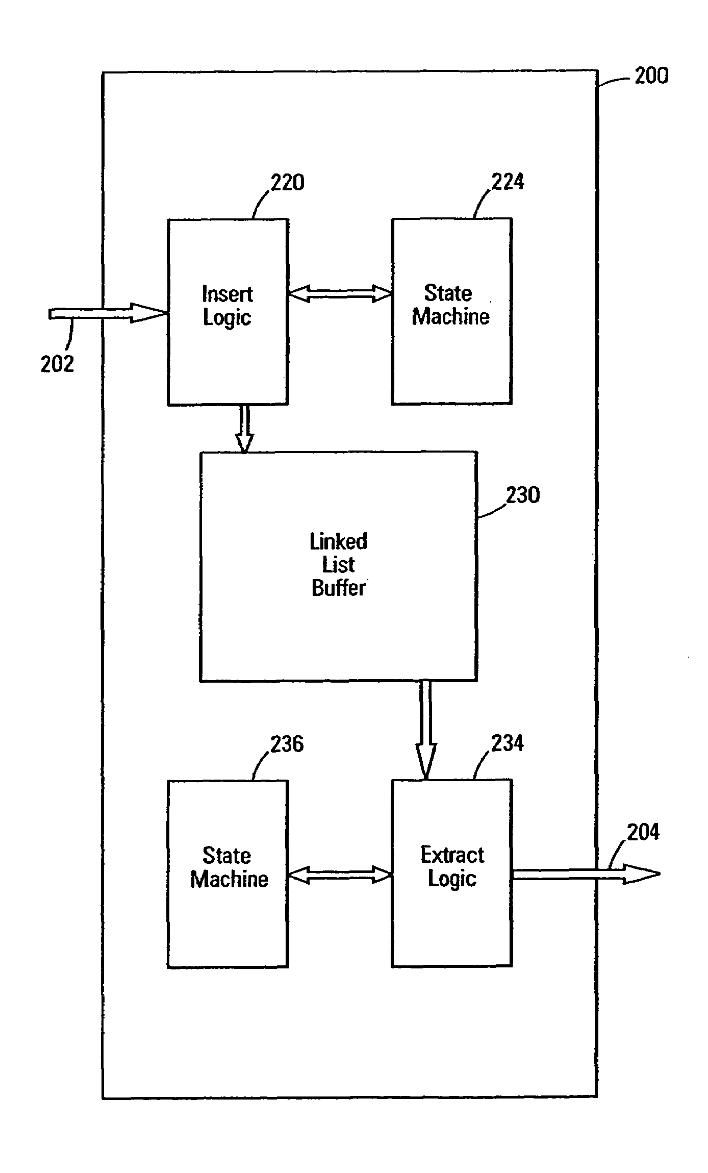
[0042]Referring to FIG. 4, linked list buffer 200 circuitry includes insert logic 220 that takes an ATM cell from a selected LVDS port and stores it in the buffer 230 in connection with a previous ATM cell received on the same linked list. The linked list numbering is explained in detail below. A first state machine 224 is provided to control the operation of the insert logic 220. The linked list buffer 200 also includes extraction logic 234 that takes ATM cells from selected linked lists and outputs the ATM cells to the UTOPIA interface. A second state machine 236 is coupled to control the operation of the extraction logic 234.

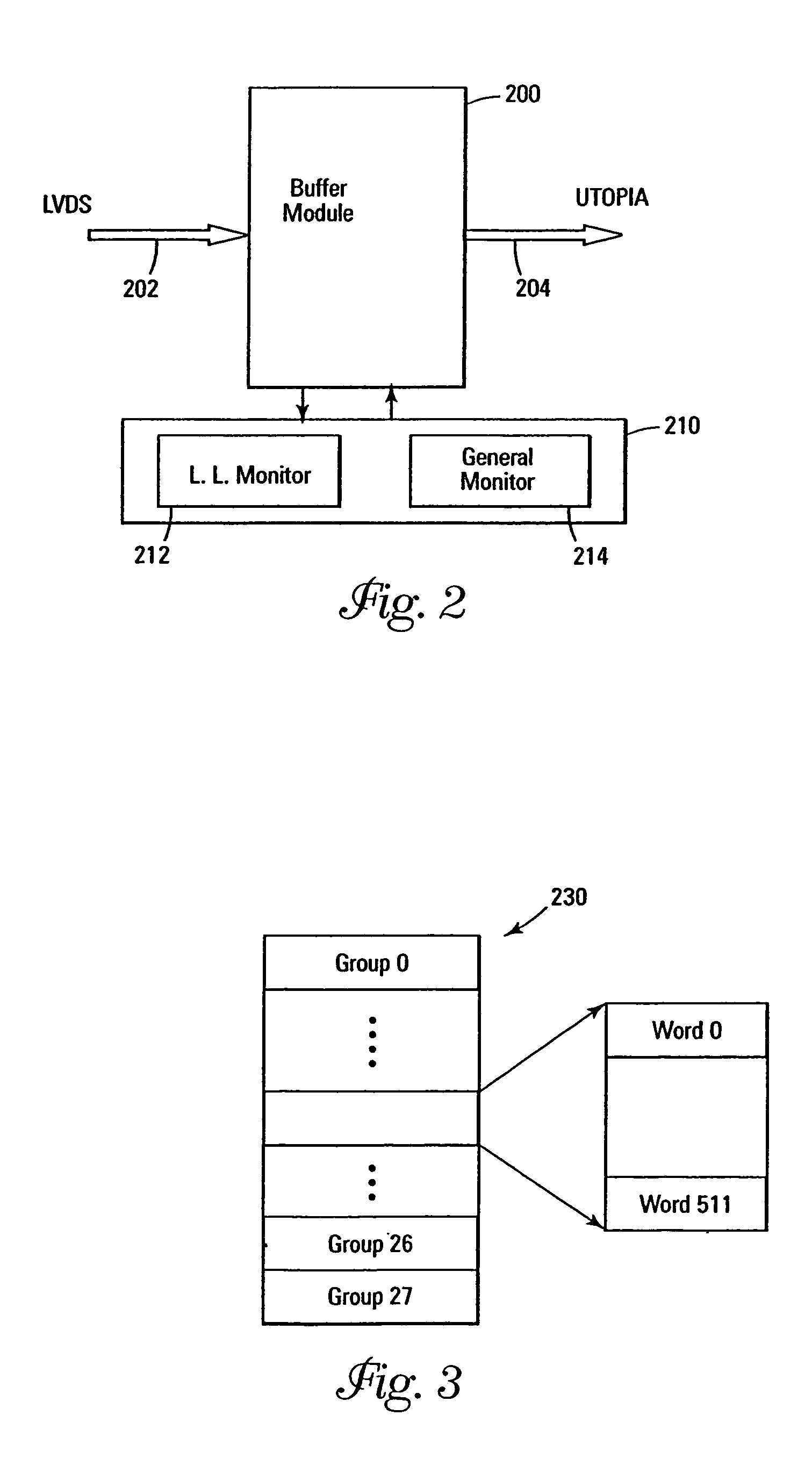
[0043]Referring to FIGS. 5a and 5b, a detailed diagram of one embodiment of the linked list buffer monitor 212 is described. The link list monitor 212 includes up / down counter circuits that have adjustable counting thresholds. The first and second state machines that control the insert and extract logic, respectively, also control the linked list monitor. The...


PUM


Abstract

A linked list buffer circuit can be configured to store different linked lists. The buffer includes insert logic and an insert state machine to add ATM cells to the linked lists in the buffer. Extract logic and an extract state machine allow for the removal of ATM cells from the linked lists in the buffer. Because, ATM cells can have different levels of priority, programmable monitor circuitry is provided to monitor the linked lists in the buffer. The monitor circuitry keeps track of buffer and list capacity, and also keeps track of cell loss priority and delay priority cells of the buffer and the linked lists. This information is used to drop received cells if necessary. The linked list monitor circuitry can be configured based upon the linked list configuration of the buffer. The linked list monitor can be configured by changing threshold levels provided to counter / comparator circuitry. Assignments of internal counter circuitry are also programmable based upon the buffer configuration.

Description

TECHNICAL FIELD OF THE INVENTION[0001]The present invention relates generally to communication buffers and in particular the present invention relates to asynchronous transfer mode (ATM) buffer systems.BACKGROUND OF THE INVENTION[0002]ATM (Asynchronous Transfer Mode) is a network technology for both local area networks (LANs) and wide area networks (WANs) that supports real-time voice and video as well as data. The topology uses switches that establish a logical circuit from communication end to end, which guarantees a quality of service for transmissions. However, unlike telephone switches that dedicate circuits end to end, unused bandwidth in ATM's logical circuits can be appropriated whenever available. For example, idle bandwidth in a videoconference circuit can be used to transfer data.[0003]ATM works by transmitting all traffic using fixed-length, 53-byte, cells. This fixed unit allows very fast switches to be built, because it is much faster to process a known packet size tha...

Claims


Application Information

Patent Timeline
IPC IPC(8): H04L12/28H04L12/56H04L29/06
CPCH04L12/5602H04L29/06H04L47/24H04L47/29H04L47/30H04L47/32H04L49/90H04L49/9078H04L2012/5681H04L9/40
Inventor RESHEF, KOBYPARCHAK, YOCHAICOHENSHYKEN, DAVID
Owner TELEDATA NETWORKS
Learn More