
Multi tip clearance measurement system and method of operation

Inactive Publication Date: 2007-05-08
GENERAL ELECTRIC CO
View PDF7 Cites 77 Cited by
  • Summary
  • Abstract
  • Description
  • Claims
  • Application Information

AI Technical Summary

Problems solved by technology

Unfortunately, an error in this gain, or a drift over a period time causes the system performance to deteriorate.
Again, error correction of individual gain of the probe tips is not addressed in such systems.
Unfortunately, these existing systems are ineffective for in-service measurements due to the noise and drift generated by changes in the geometry of the components, among other factors.
As the components become worn during service, the offline measurements become ineffective for in-service clearance control.

Method used


Image

  • Multi tip clearance measurement system and method of operation
  • Multi tip clearance measurement system and method of operation
  • Multi tip clearance measurement system and method of operation

Examples


Embodiment Construction

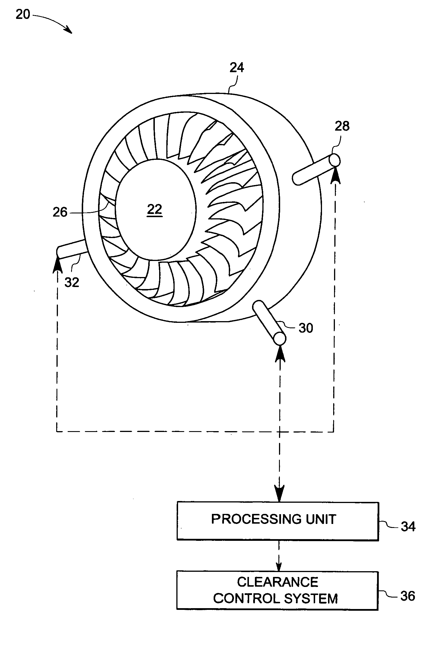
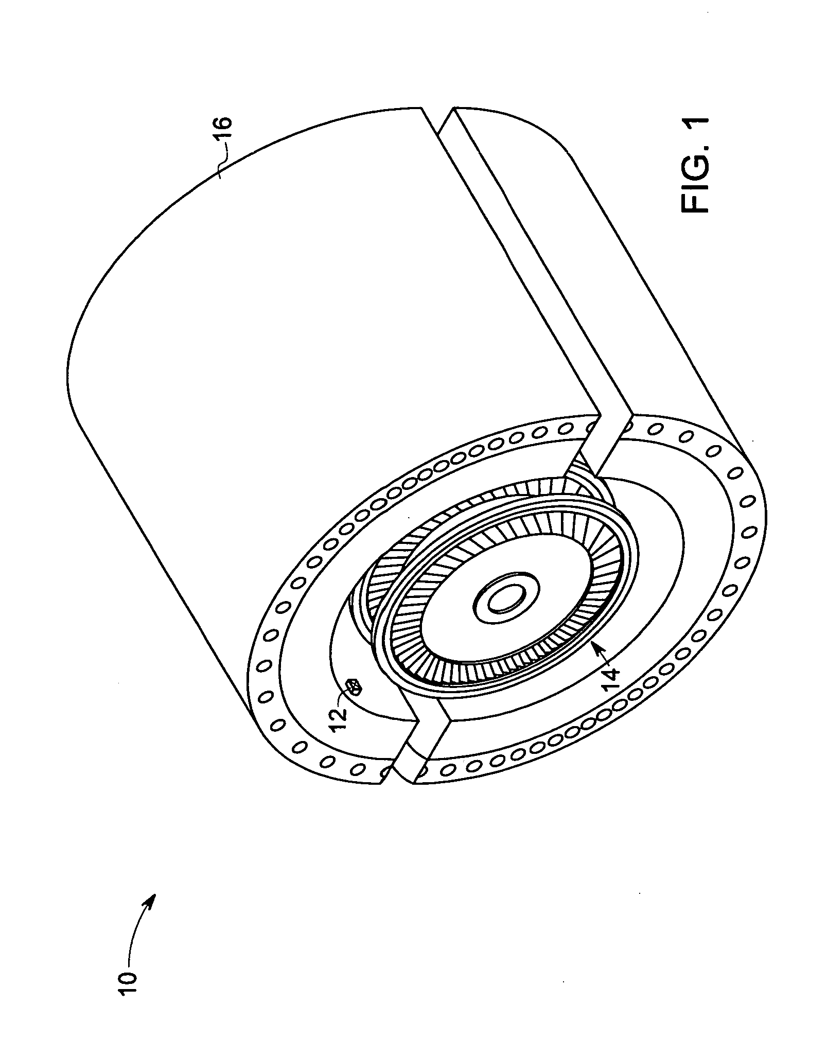
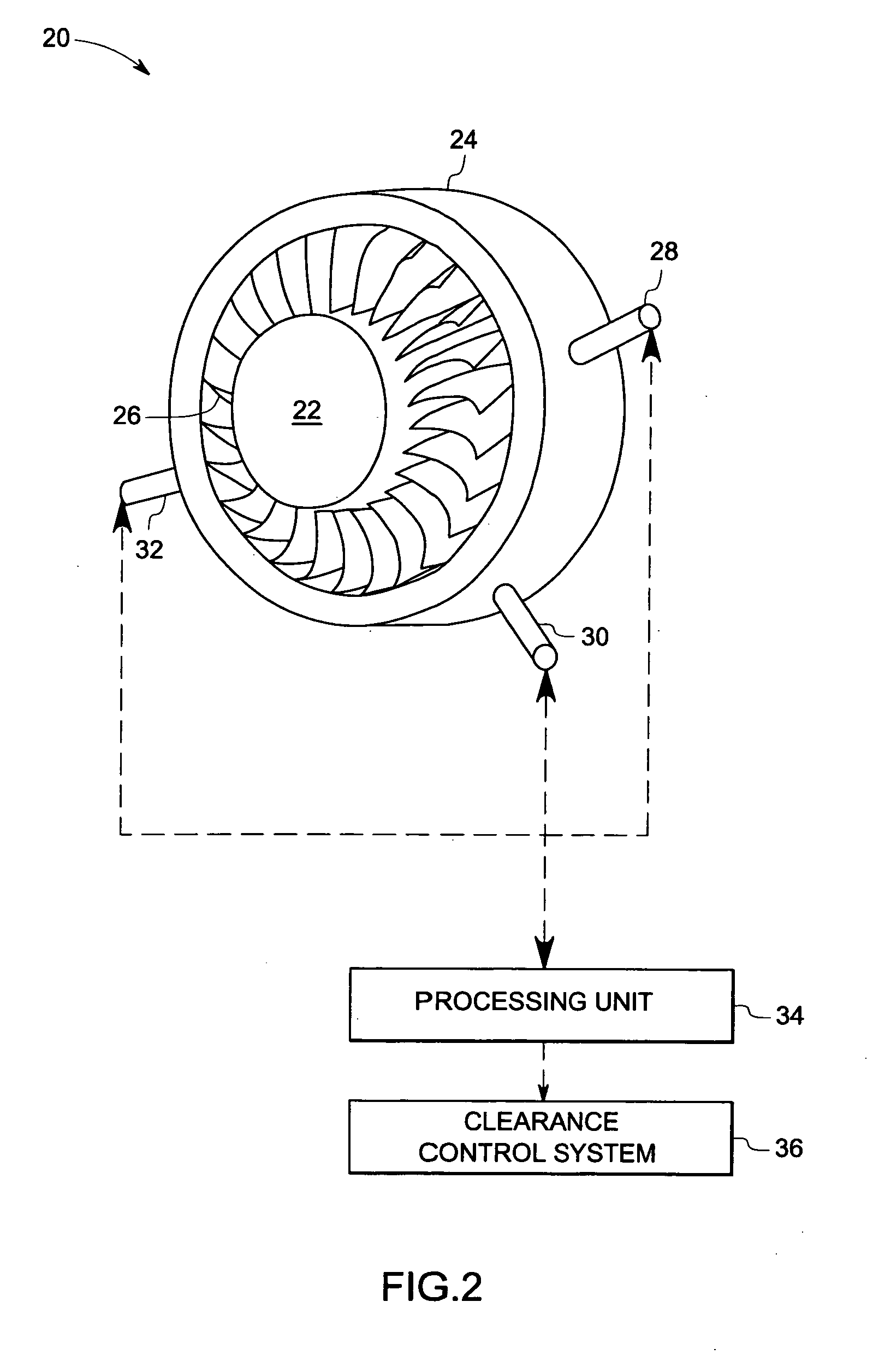
[0018]As discussed in detail below, embodiments of the present technique function to provide an accurate measurement of clearance between two objects in various systems such as a steam turbine, a generator, a turbine engine (e.g., airplane turbine engine), a machine having rotating components and so forth. In particular, the present technique employs a signal correlation method for gain error correction in a radial and axial clearance measurement system to detect and correct for probe tip errors and drifts. Referring now to the drawings, FIG. 1 illustrates a steam turbine 10 having a multi tip clearance measurement system 12 for measuring a clearance between two objects in the steam turbine 10. In the illustrated embodiment, the clearance measurement system 12 includes a sensor having a plurality of probe tips that is configured for measuring the clearance between a rotating component 14 and a stationary component 16 in the steam turbine 10, which will be described in detail below.

[...


PUM


Abstract

A multi tip clearance measurement system is provided. The clearance measurement system includes a sensor disposed on a first object, wherein the sensor comprises a plurality of probe tips configured to generate signals representative of a sensed parameter corresponding to a second object and a processing unit configured to evaluate the signals from subsets of the sensed parameters from the probe tips to detect an outlier probe tip and to adjust a gain, or an offset of the respective outlier probe tip for estimating the clearance between the first and second objects based upon the signals.

Description

BACKGROUND[0001]The invention relates generally to clearance measurement systems, and more particularly to, a multi tip clearance measurement system for measuring a clearance between a stationary component and a movable component of a rotating machine.[0002]Various types of sensors have been used to measure the distance between two objects. In addition, these sensors have been used in various applications. For example, a steam turbine has a rotating bucket that is disposed adjacent a carrier. The clearance between the rotating bucket and the carrier varies due to various operating conditions, such as changes in temperature, oxidation of the bucket tip, and so forth. It is desirable that a gap or clearance between the rotating bucket and the carrier be maintained during operation of the steam turbine.[0003]One existing sensor is a multi tip capacitance sensor that includes multiple probe tips to measure capacitance for estimating the radial and axial clearance between stationary and ...

Claims


Application Information

Patent Timeline
IPC IPC(8): G01R27/26
CPCF01D21/003G01B7/14F05D2260/80G01B21/16
Inventor ANDARAWIS, EMAD ANDARAWISDASGUPTA, SAMHITAMANI, SHOBHANACHEN, WEIGUO
Owner GENERAL ELECTRIC CO
Learn More