
Ink-jet head

a technology of inkjet head and inkjet printing, which is applied in the direction of printing and inking apparatus, etc., can solve the problems of reducing affecting the discharge accuracy of the inkjet head, so as to achieve the effect of improving the discharge accuracy

Active Publication Date: 2007-05-08
BROTHER KOGYO KK
View PDF14 Cites 8 Cited by
  • Summary
  • Abstract
  • Description
  • Claims
  • Application Information

AI Technical Summary

Benefits of technology

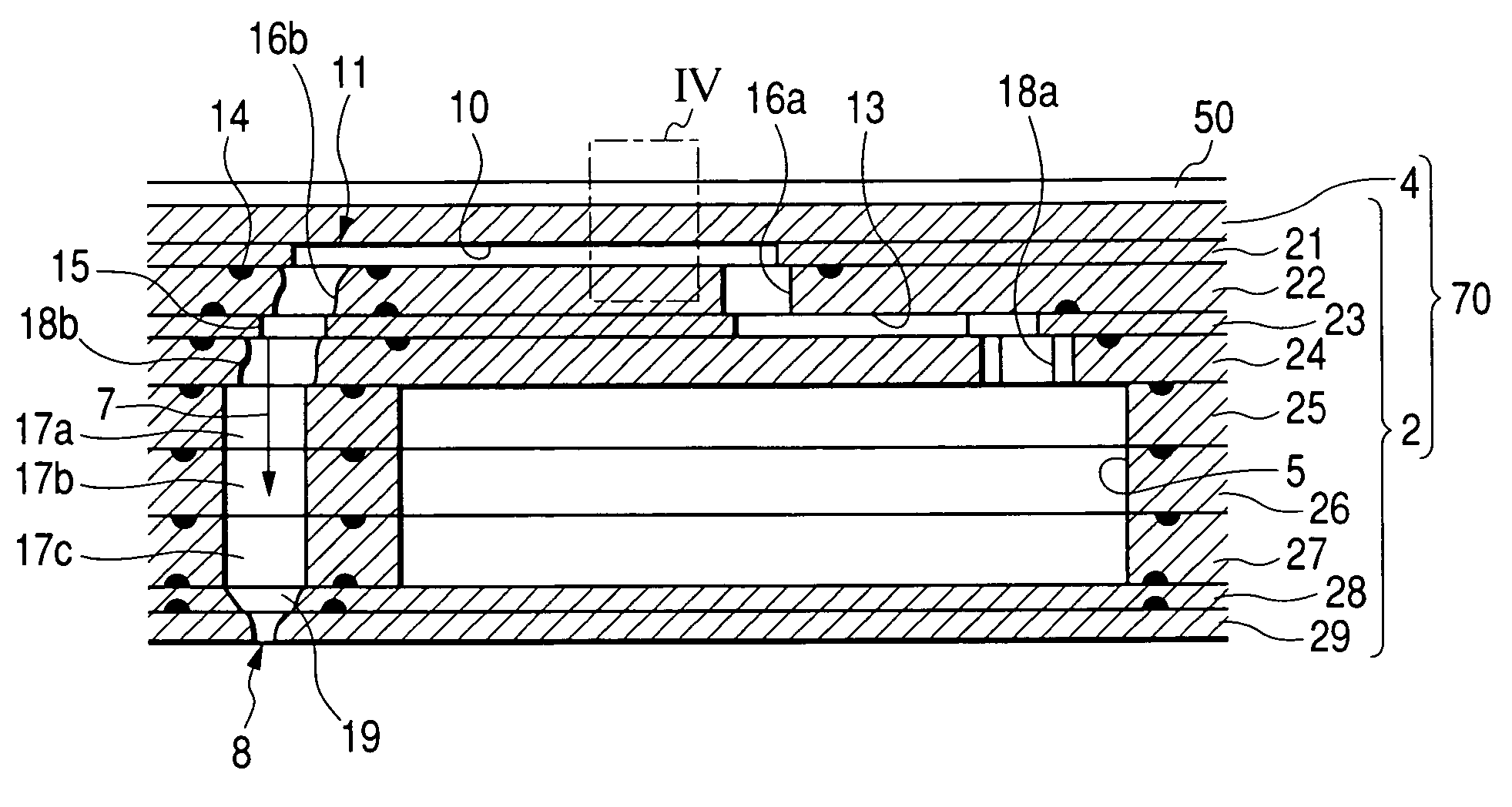
The invention provides an ink-jet head that prevents blockages in the ink flow path and improves discharge accuracy. This is achieved by using a manifold and plural discharge elements with plural dummy paths formed between them. The dummy paths are positioned around the discharge element group and are formed by opening parts in plural layers including at least one opening part communicating with the manifold. The opening parts are pushed out towards the discharge element group from the outside of the discharge element group by lamination, and the flow of adhesive is blocked in the dummy paths. The plural plates include a nozzle layer, a pressure chamber layer, a manifold layer, and an aperture layer, and each dummy path includes an opening part formed in the aperture layer to have the same shape as an aperture in the manifold layer. The dummy paths, together with the plural discharge elements, are disposed at the specified intervals. The opening parts are formed as through holes passing through the layers in which they are formed, and the dummy paths are formed as communicating holes in which the through holes communicate with each other.

Problems solved by technology

Thus, there has been a problem that the ink flow path is blocked by the adhesive, and the discharge accuracy of the ink-jet head is lowered.
However, in the ink-jet head disclosed in Japanese Patent Application No. 2002-280581, when the amount of adhesive pushed out from the outside of the discharge element group toward the inside by lamination becomes large, there has been a fear that the adhesive overpasses the opening part and flows into the through hole forming the pressure chamber.
Besides, even if the flow of the adhesive into the pressure chamber is prevented, there has also been a problem that the adhesive flows into a through hole of another layer forming the ink flow path and the ink flow path is blocked.

Method used


Image

  • Ink-jet head
  • Ink-jet head
  • Ink-jet head

Examples


Embodiment Construction

[0035]Hereinafter, embodiments of the invention will be described with reference to the drawings.

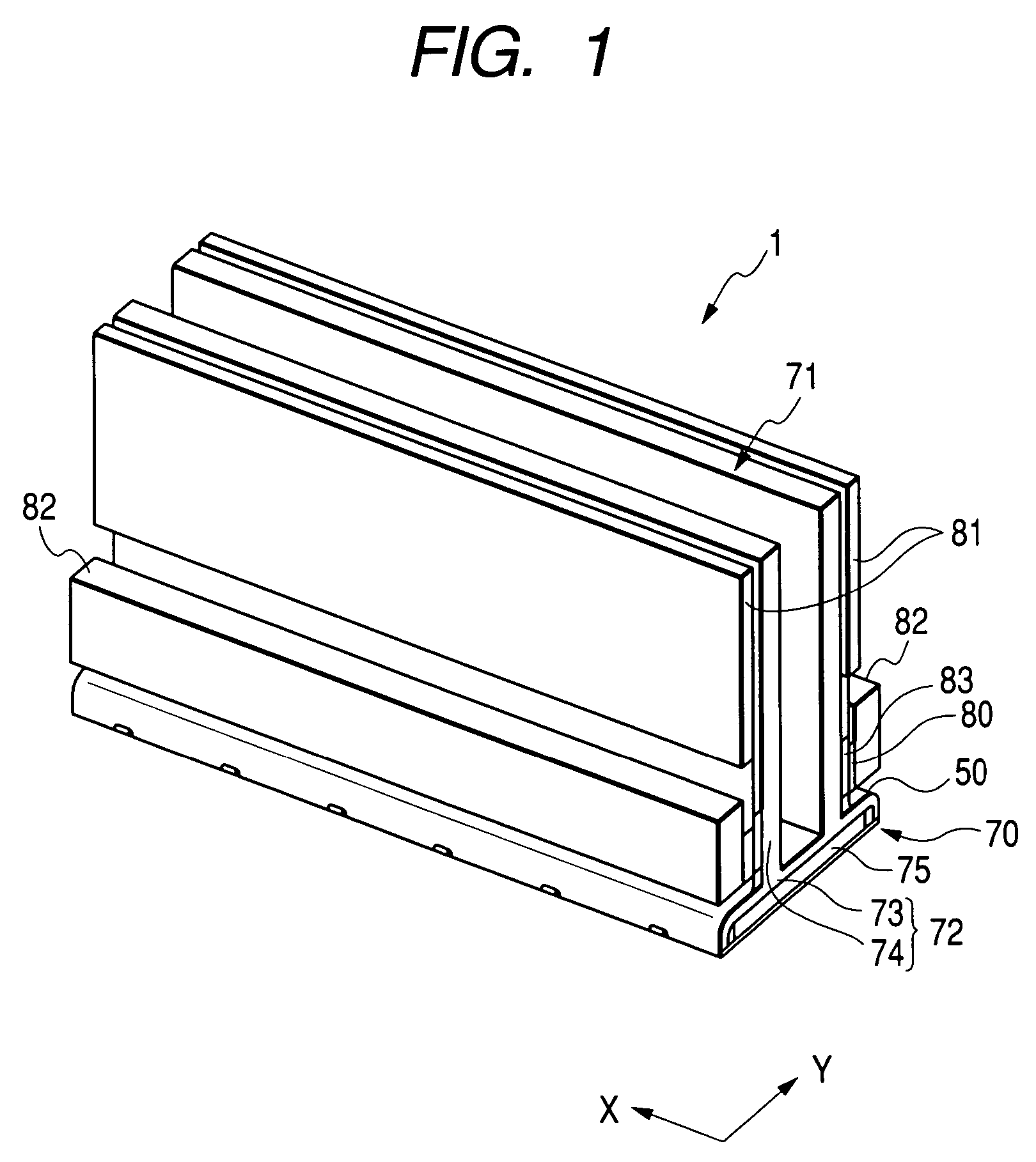
[0036]FIG. 1 is a perspective view showing an ink-jet head of an embodiment. In an ink-jet head 1, a head unit 70 disposed to be opposite to a recording sheet is held by a base part 71. The ink-jet head 1 is scanned in an X direction (main scanning direction), and the recording sheet is transported in a Y direction (sub-scanning direction), so that recording can be performed on the recording sheet.

[0037]The head unit 70 includes a flow path unit 2 in which a flow path including a pressure chamber 10, a nozzle 8 and the like is constructed, and an actuator unit 4 for pressurizing ink in the pressure chamber 10 (see FIGS. 2 and 4), and discharges the ink to a specified position of the recording sheet. The base part 71 includes a base block 75 and a holder 72. The base block 75 is fixed to the back side of the head unit 70, and supports the head unit 70 formed to be thin and reinforces its ...


PUM


Abstract

In an ink-jet head including a discharge element group in which discharge elements each including a nozzle for discharging ink and a pressure chamber for applying a discharge pressure to the ink supplied from a manifold are disposed at specified intervals, a manifold and plural discharge elements are formed of through holes provided in plural thin plates bonded with adhesive and laminated, and plural dummy paths positioned around the discharge element group are formed of opening parts provided to communicate with each other in the plural thin plates.

Description

BACKGROUND OF THE INVENTION[0001]1. Field of the Invention[0002]The present invention relates to an ink-jet head provided in a printer or the like, and particularly to an ink-jet head including a discharge element group in which plural discharge elements for discharging ink are disposed.[0003]2. Description of the Related Art[0004]An ink-jet head used for a printer, a facsimile or the like is formed of plural thin plates which are bonded with adhesive and are laminated. Through holes are provided in each of the thin plates, and by the through holes, a discharge element group is formed in which plural discharge elements having ink flow paths are disposed.[0005]Each of the discharge elements includes a nozzle for discharging ink, and a pressure chamber communicates with the nozzle. A manifold for supplying ink is provided to communicate with the pressure chamber. An aperture for restricting the flow amount of ink is formed between the manifold and the pressure chamber. An actuator suc...

Claims


Application Information

Patent Timeline
Patent Type & Authority Patents(United States)
IPC IPC(8): B41J2/045B41J2/055B41J2/14B41J2/16
CPCB41J2/14209B41J2002/14217B41J2002/14225B41J2002/14306B41J2002/14362B41J2002/14459B41J2202/20
Inventor CHIKAMOTO, TADANOBU
Owner BROTHER KOGYO KK
Learn More