
Control housing for work vehicle

a control housing and work vehicle technology, applied in the field of work vehicles, to achieve the effect of less chance of failure, easy assembly, and low cos

Inactive Publication Date: 2007-05-08
DEERE & CO
View PDF26 Cites 14 Cited by
  • Summary
  • Abstract
  • Description
  • Claims
  • Application Information

AI Technical Summary

Benefits of technology

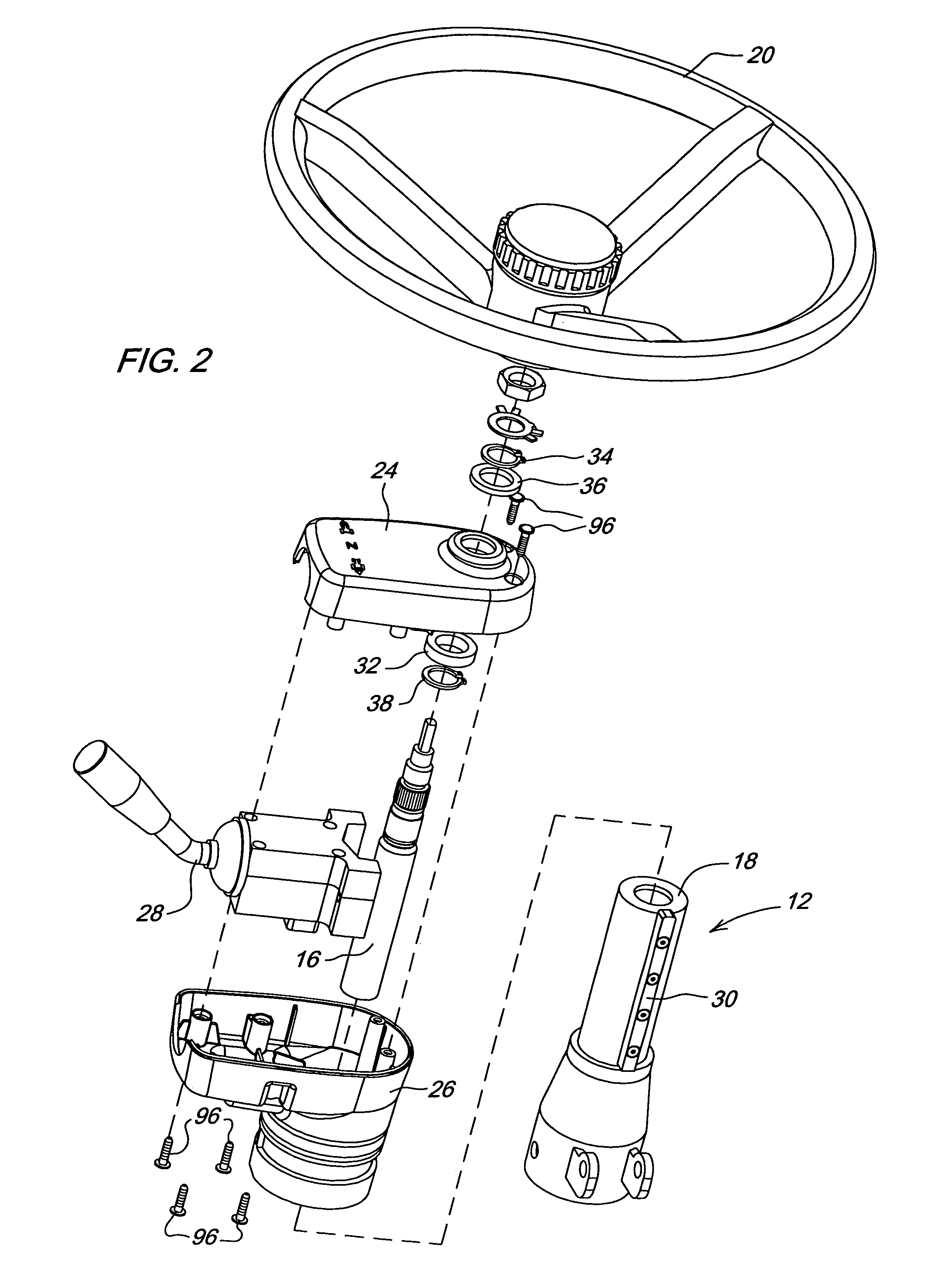
[0004]The present invention has upper and lower housings that together retain the control lever. These two housing halves are fastened together with a plurality of fasteners, and other joining techniques. The lever is retained between the two housing halves without additional fasteners. More particularly, the lever is “sandwiched” between the two housing halves. As the lever has a load applied to it, the load is transmitted to the housing halves which, in turn, transmit the load to the steering column. The housing halves slide on the steering column allowing the steering column to telescope while maintaining a constant distance from the steering wheel to the reverser lever. There is also bushing means that prevents the housing from wearing prematurely as the steering wheel is turned. This differs from the known prior art in that the electronic power reverser is housed between two composite parts that provide both the aesthetic and structural functions. The benefit is that the disclosed system that has fewer parts, is lower cost, and is easier to assemble than previously known structures. This design is more fully integrated and has less opportunity for failure than known structures.
[0009]An additional object of the invention is the provision of a housing for a control lever assembly that requires fewer parts, is lower in cost and is easier to assemble than previously known housings.

Problems solved by technology

The problem is that there is a need for a housing that encloses and holds a control lever such as the electronic power reverser control for an agriculture tractor.

Method used


Image

  • Control housing for work vehicle
  • Control housing for work vehicle
  • Control housing for work vehicle

Examples


Embodiment Construction

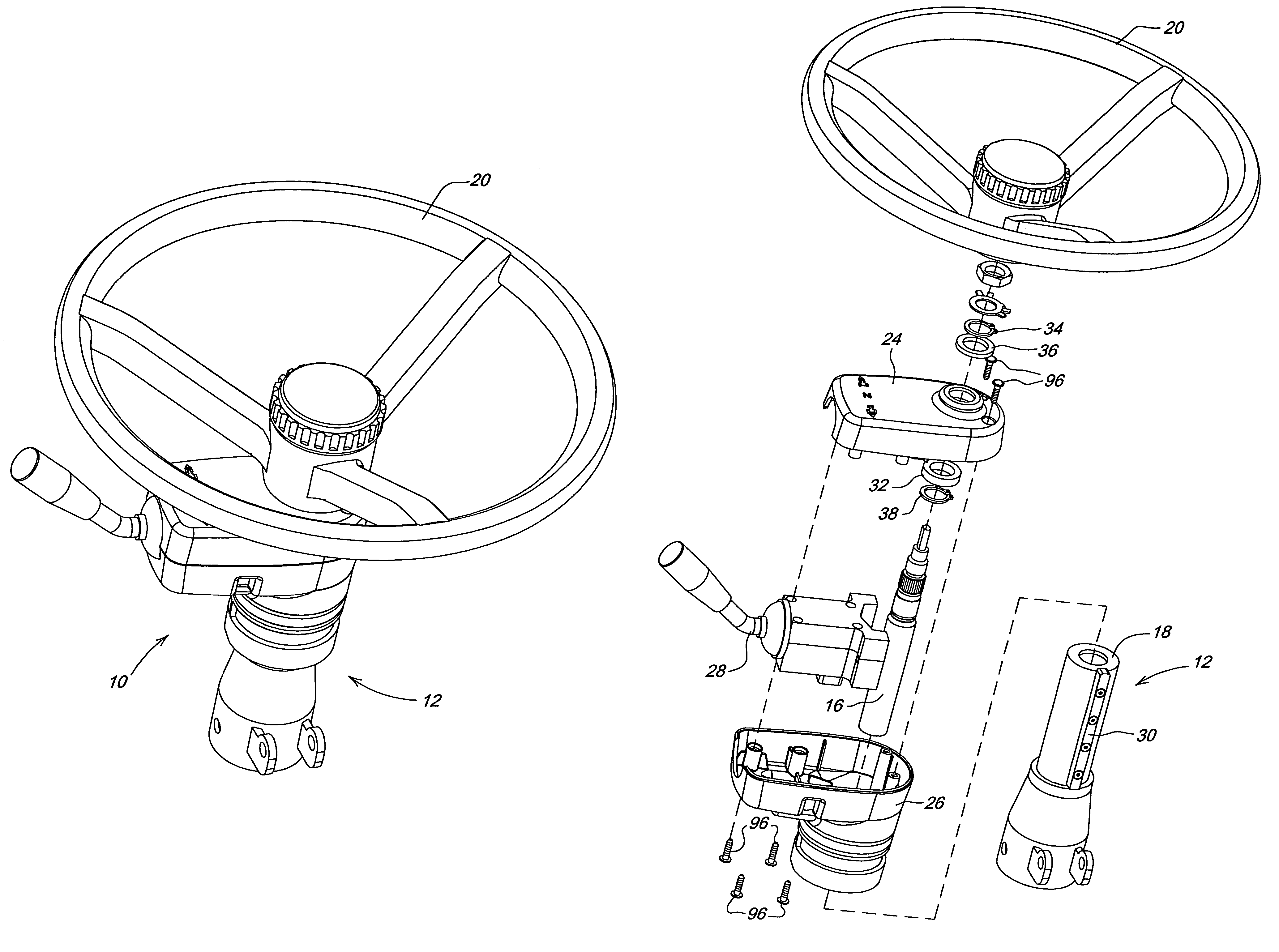
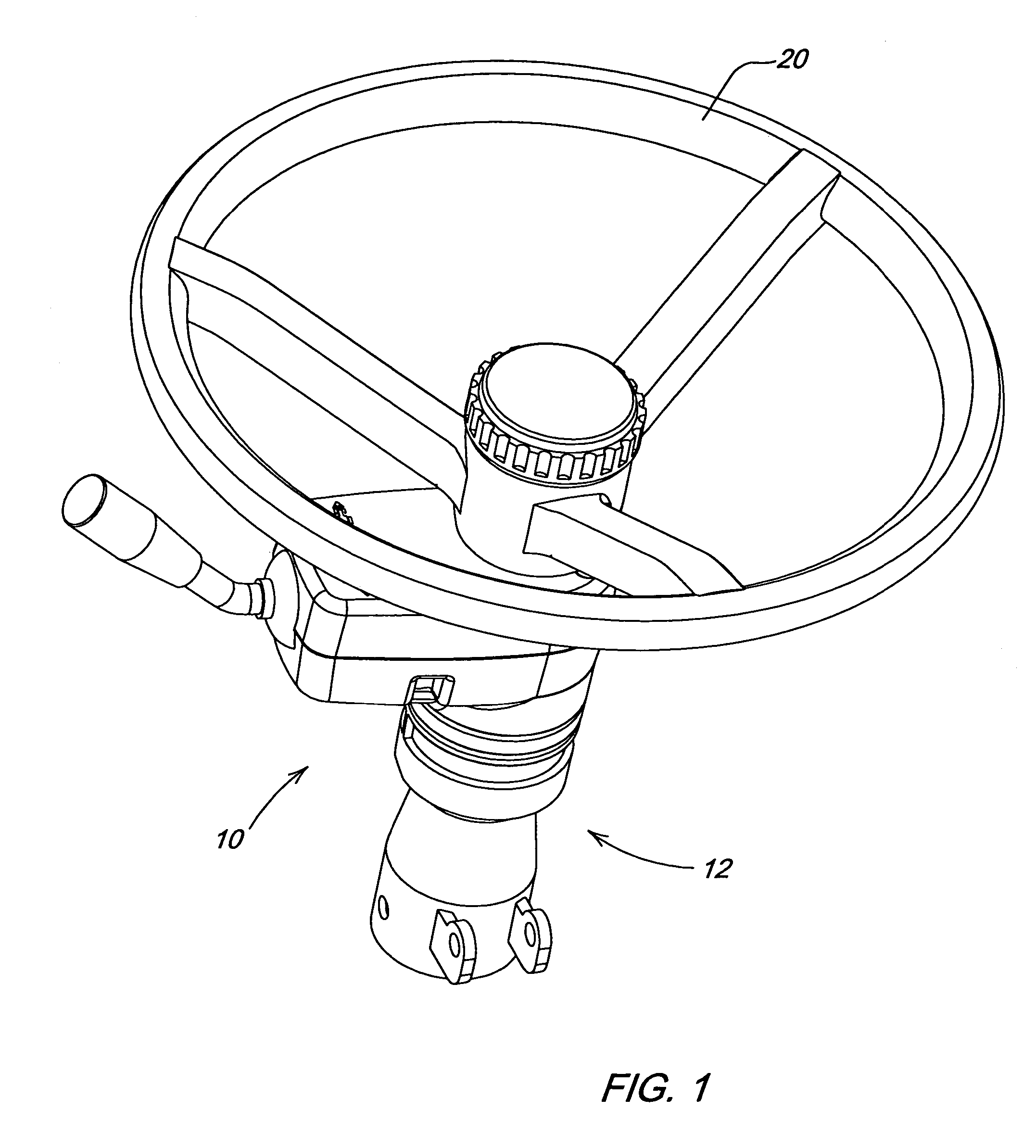
[0025]With reference now to the drawings it can be seen that an operator control housing assembly according to the invention is designated generally by the numeral 10. As shown in FIGS. 1 and 2 the control housing 10 is adapted for mounting on a steering control assembly 12 in an operator's station of a vehicle. The steering control assembly 12 generally includes a steering column comprised of a steering shaft 16 and a steering shaft barrel 18. A steering wheel 20 is mounted to the steering shaft 16. The steering control assembly 12 is operatively connected, in a conventional manner, with a steering linkage of the vehicle (not shown). In the preferred embodiment the steering control assembly 12 is further adapted so that the steering shaft 16 is slidable with respect to the steering barrel 18 so that the steering column and wheel 20 are able to be telescoped. The steering column is also adapted to tilt, as well as telescope, to facilitate entry and egress from the operator station a...


PUM


Abstract

An agricultural tractor or other work vehicle having an operator's station is described. A steering column assembly is mounted in the operator's station and has a steering shaft disposed in a steering shaft barrel. The steering column assembly is adapted to both tilt and telescope. A left hand forward-neutral-reverse lever is mounted in a housing. A key is mounted on the steering shaft barrel and a first housing half is journaled on the steering shaft by way of a bushing. The first housing half has a plurality of lever support bolsters and a plurality of fastener bosses. A second housing half is disposed on the steering shaft barrel and has a plurality of lever support bolsters, a keyway and a plurality of fastener bosses. One of the first or second housing halves has a groove around a peripheral edge thereof, the other of the first or second housing halves has a tongue around a peripheral edge thereof. Similarly, one of the first or second housing halves has a circular lip at an end of each fastener boss. The keyway of the second housing half engages the key mounted on the steering barrel so that the housing cannot rotate with respect thereto and the tongue of one housing half matingly engages the groove of the other housing half, while the circular lips of the fastener bosses of one housing half engage the fastener bosses of the other housing half. The left hand forward-neutral-reverse lever is sandwiched between the upper and lower housings and is supported therein by the lever support bolsters of both housing halves so that loads are transmitted from the left hand forward-neutral-reverse lever to the housing assembly and in turn to the steering column assembly. The control housing assembly is able to move with the steering shaft and steering wheel as the steering shaft and steering wheel are telescoped and tilted, but cannot rotate.

Description

FIELD OF THE INVENTION[0001]The present invention relates generally to work vehicles such as agricultural tractors. More particularly, the present invention relates to operator controls within the operator's stations of such vehicles. Specifically, the present invention relates to housings for such operator controls.BACKGROUND OF THE INVENTION[0002]The problem is that there is a need for a housing that encloses and holds a control lever such as the electronic power reverser control for an agriculture tractor. This housing must withstand loads applied to the lever as well as be aesthetically pleasing. It is desirable to do this with as few parts are possible.[0003]Any tractor or other work vehicle that has an electronic power reverser will have a lever / switch that controls the forward / rearward motion of the vehicle. Of the known power reverser housings, none use a composite material to form both the aesthetic housing as well as the structural functions.SUMMARY OF THE INVENTION[0004]T...

Claims


Application Information

Patent Timeline
Patent Type & Authority Patents(United States)
IPC IPC(8): B62D1/16
CPCB60Q1/1469B62D1/16F16H59/02B60K20/06F16H2059/0256B60Q2800/20
Inventor UEHLE, HOWARD THOMASSHUTTLEWORTH, ADAM JOE
Owner DEERE & CO
Learn More