Polarization-shaped duobinary optical transmission apparatus
a transmission apparatus and duobinary technology, applied in the field of optical transmission apparatuses, can solve the problems of reducing the reliability and reproducibility of its implementation, limiting the enlargement of the transmission capacity, and affecting the reliability of its implementation, so as to reduce the complexity of its structure and reduce the cost of implementation
- Summary
- Abstract
- Description
- Claims
- Application Information
AI Technical Summary
Benefits of technology
Problems solved by technology
Method used
Image


Examples
first embodiment
[0031]FIG. 3 illustrates the structure of a polarization-shaped duobinary optical transmission apparatus according to the present invention, and FIG. 4 illustrates signal forms at nodes A, B, C and D in FIG. 3.
[0032]With reference to FIG. 3, the polarization-shaped duobinary optical transmission apparatus includes a light source 101, which generates light having a continuous wave, an optical intensity modulator 103, which converts the light having the continuous wave into an optical intensity signal by an input electric signal, a differential encoder 104, which encodes the input electric signal, a half-bit delay element 105, which delays a 2-level electric signal by a half-bit, and polarization modulator 107, which polarization-modulates the 2-level electric signal delayed by a half-bit. Also, the polarization-shaped duobinary optical transmission apparatus includes modulator operation amplifiers 102 and 106.
[0033]The light source 101 may be, for example, a laser diode.
[0034]The opt...
second embodiment
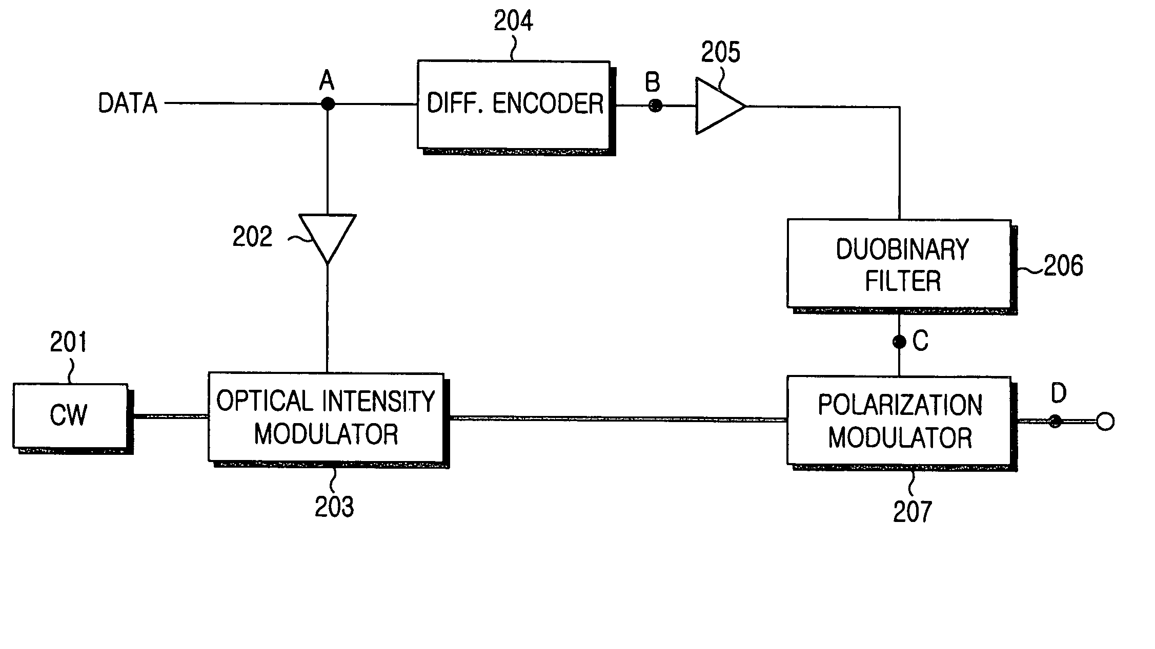
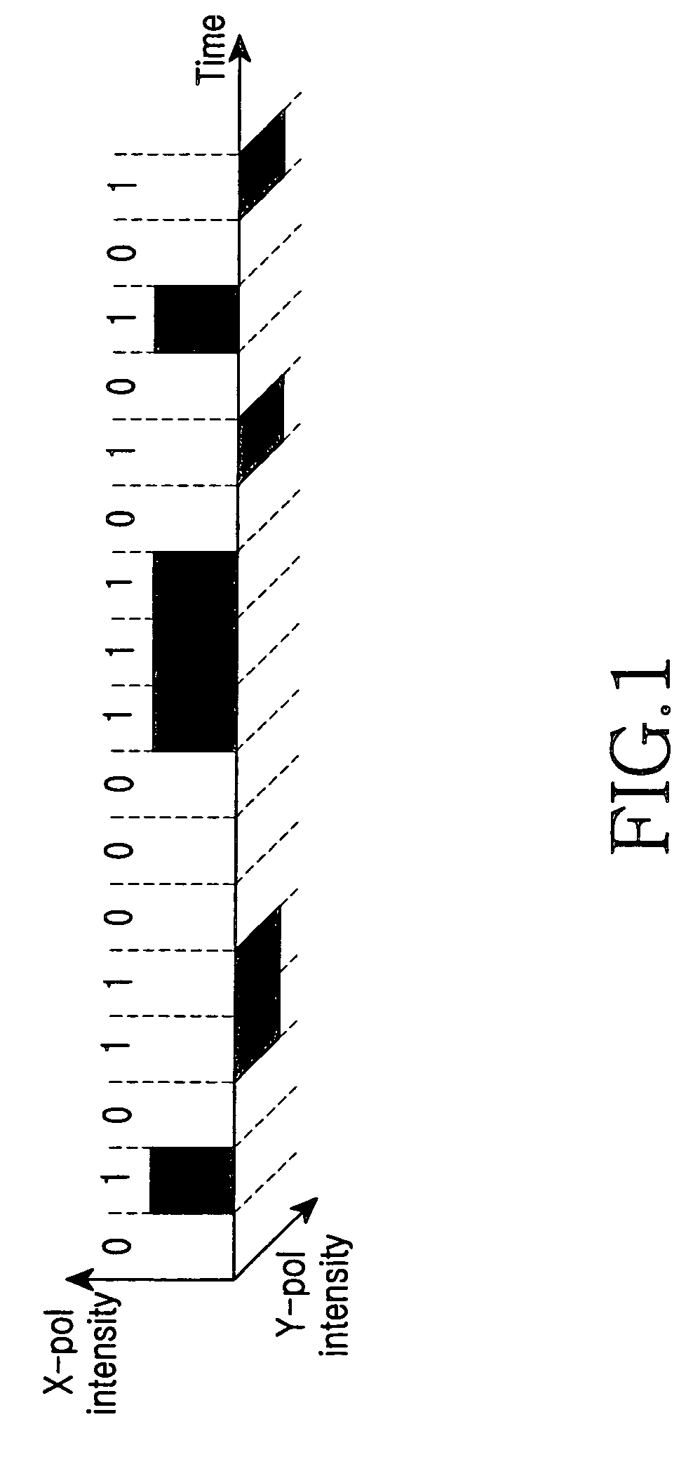
[0040]FIG. 5 illustrates the structure of a polarization-shaped duobinary optical transmission apparatus according to the present invention, and a, b, c and d in FIG. 6 illustrate forms of a signal at nodes A, B, C and D in FIG. 5.
[0041]With reference to FIG. 5, the polarization-shaped duobinary optical transmission apparatus includes a light source 201, which generates light having a continuous wave, an optical intensity modulator 203, which modulates the light having the continuous wave into an optical intensity signal by an input electric signal, a differential encoder 204, which encodes the input electric signal, a duobinary filter 206, which converts the encoded 2-level electric signal into a 3-level electric signal and a polarization modulator 207, which polarization-modulates the signal modulated optical intensity by means of the electric signal converted into a 3-level signal. Also, the polarization-shaped duobinary optical transmission apparatus includes modulator operation...
third embodiment
[0045]FIG. 7 illustrates the structure of a polarization-shaped duobinary optical transmission apparatus according to the present invention. This embodiment is using a Mach-Zehnder modulator.
[0046]With reference to FIG. 7, a polarization-shaped duobinary optical transmission apparatus, includes a light source 301, a differential encoder 302, an operation amplifier 303, a duobinary filter 304 and an optical modulator 310.
[0047]The light source 301 generates light having a continuous wave and may be, for example, a laser diode.
[0048]The differential encoder 302 encodes an input 2-level NRZ data and may be, for example, a power splitter, a 1-bit delay element and a power combiner.
[0049]The duobinary filter 304 is a low pass filter having a bandwidth corresponding to about ¼ data transmission speed (˜0.25 transmission speed). This filter 304 converts the inputted 2-level signal into a 3-level signal having three logical level, +1, 0, −1,.
[0050]The optical modulator 310 includes a polari...
PUM
| Property | Measurement | Unit |
|---|---|---|
| angle | aaaaa | aaaaa |
| optical intensity | aaaaa | aaaaa |
| power level | aaaaa | aaaaa |
Abstract
Description
Claims
Application Information
 - R&D
- Intellectual Property
- Life Sciences
- Materials
- Tech Scout
- Unparalleled Data Quality
- Higher Quality Content
- 60% Fewer Hallucinations
Browse by: Latest US Patents, China's latest patents, Technical Efficacy Thesaurus, Application Domain, Technology Topic, Popular Technical Reports.
© 2025 PatSnap. All rights reserved.Legal|Privacy policy|Modern Slavery Act Transparency Statement|Sitemap|About US| Contact US: help@patsnap.com