Display device and driving method thereof
a technology of a display device and a driving method, applied in the direction of static indicating devices, high-level techniques, instruments, etc., can solve the problems of inability to reduce the power consumption less, and large power consumption of the dck oscillation circuit 106. to achieve the effect of reducing the average power consumption
- Summary
- Abstract
- Description
- Claims
- Application Information
AI Technical Summary
Benefits of technology
Problems solved by technology
Method used
Image

Examples
embodiment 1
[Embodiment 1]
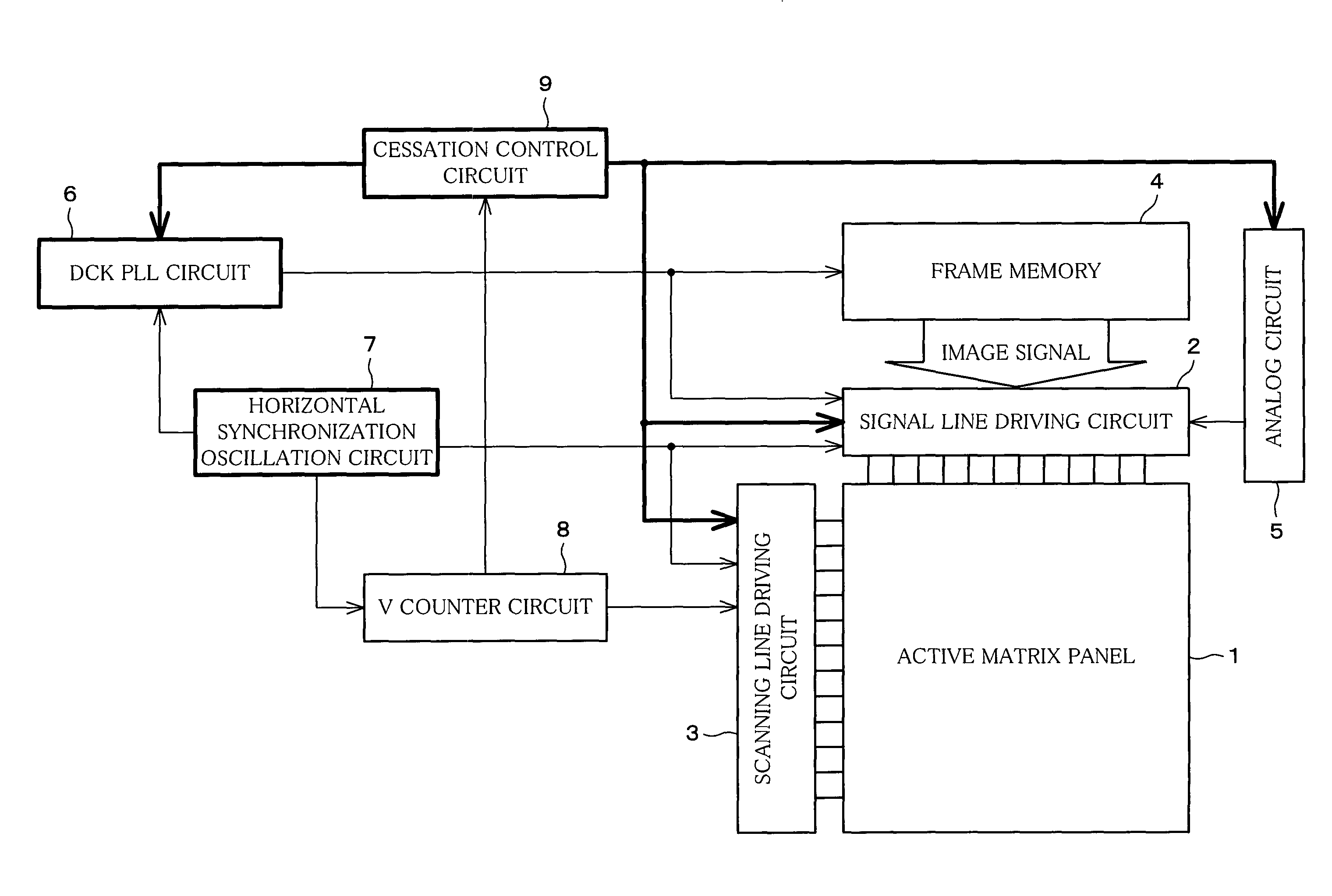
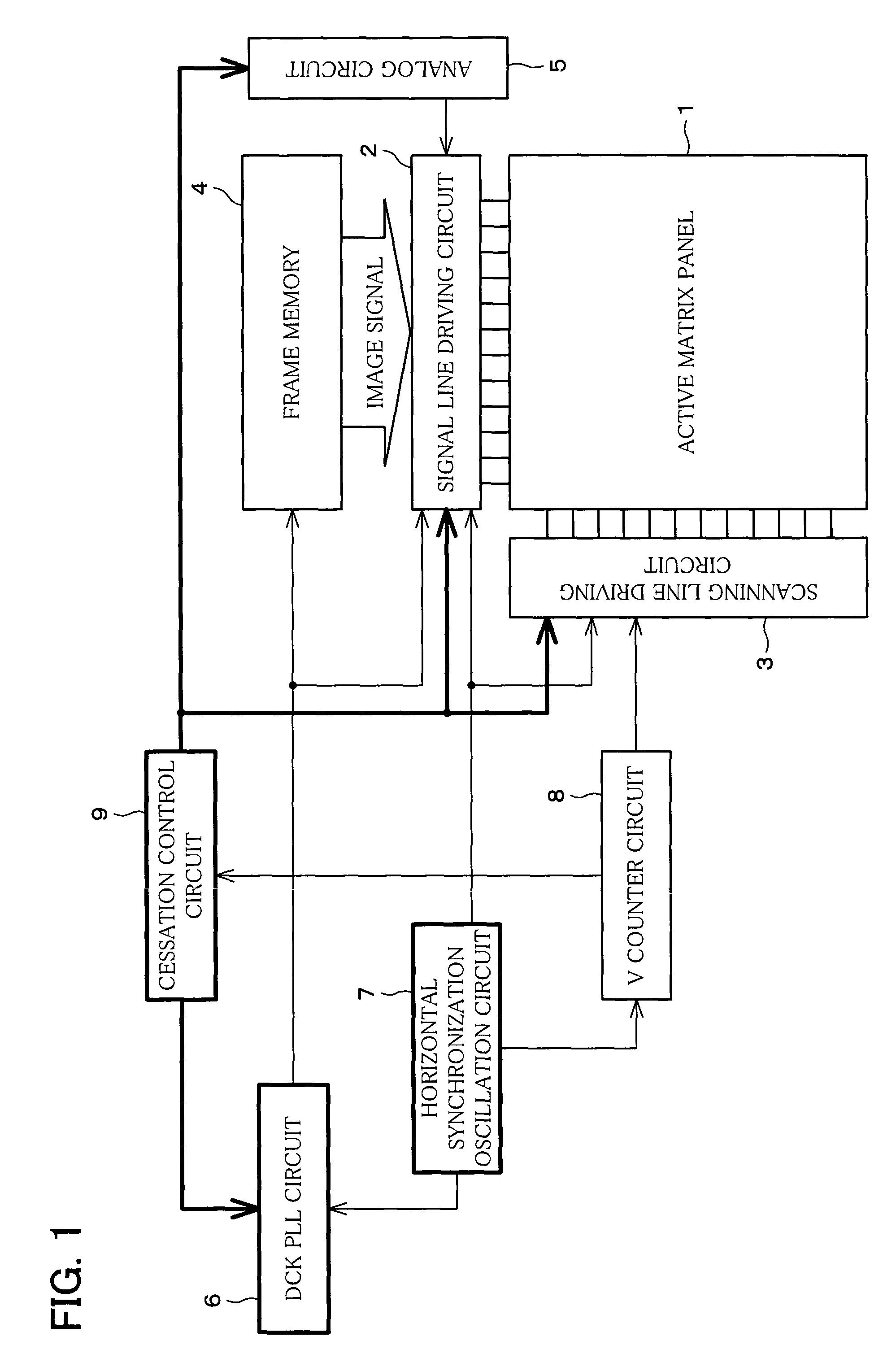
[0065]The following will explain one embodiment of the present invention. This embodiment uses a display device which selects each line of a screen provided in a display section and having pixels aligned in a matrix manner by applying a scanning signal to a scanning signal line of the pixel of each line so as to scan the screen, and also supplies a data signal from a data signal line to the pixel of the selected line so as to carry out display. As to the driving method of the display device, the present embodiment uses an inaction driving method which provides an inaction period for stopping scanning of all scanning signal lines. The inaction period is provided between the respective scanning periods for scanning the screen.
[0066]As shown in FIG. 1, a display device according to the present embodiment includes an active matrix panel 1 having pixels which are made of liquid crystal elements and aligned in a matrix manner, a signal line driving circuit 2 for driving data...
embodiment 2
[Embodiment 2]
[0089]The following will explain another embodiment of the present invention. Note that, as with Embodiment 1, the present embodiment also uses an active matrix display device adopting the inaction driving method. Therefore, for ease of explanation, materials having the equivalent functions as those shown in the drawings pertaining to Embodiment 1 above will be given the same reference symbols, and explanation thereof will be omitted here.
[0090]As shown in FIG. 4, the display device according to the present embodiment includes a medium-speed PLL circuit (an output timing clock generation circuit) 10 and a vertical synchronization oscillation circuit (a start timing clock generation circuit) 11, which are provided respectively instead of the horizontal synchronization oscillation circuit 7 and the V counter 8 of the display device of Embodiment 1 which is shown in FIG. 1.
[0091]The vertical synchronization oscillation circuit 11 oscillates a signal by itself so as to gen...
embodiment 3
[Embodiment 3]
[0098]The following will explain still another embodiment of the present invention. Note that, as with Embodiment 2, the present embodiment also uses an active matrix display device adopting the inaction driving method. Therefore, for ease of explanation, materials having the equivalent functions as those shown in the drawings pertaining to Embodiment 2 above will be given the same reference symbols, and explanation thereof will be omitted here.
[0099]The display device according to the present embodiment includes an inaction cycle oscillation circuit (a driving control circuit) 12 and a low-speed PLL circuit (a start timing clock generation circuit) 13, which are provided respectively instead of the inaction control circuit 9 and the vertical synchronization oscillation circuit 11 of the display device of Embodiment 2 which is shown in FIG. 4.
[0100]The inaction cycle oscillation circuit 12 oscillates a signal by itself so as to generate a driving control signal Scan, a...
PUM
| Property | Measurement | Unit |
|---|---|---|
| power consumption | aaaaa | aaaaa |
| power consumption | aaaaa | aaaaa |
| average power consumption | aaaaa | aaaaa |
Abstract
Description
Claims
Application Information
 - R&D
- Intellectual Property
- Life Sciences
- Materials
- Tech Scout
- Unparalleled Data Quality
- Higher Quality Content
- 60% Fewer Hallucinations
Browse by: Latest US Patents, China's latest patents, Technical Efficacy Thesaurus, Application Domain, Technology Topic, Popular Technical Reports.
© 2025 PatSnap. All rights reserved.Legal|Privacy policy|Modern Slavery Act Transparency Statement|Sitemap|About US| Contact US: help@patsnap.com