Switching mechanism with shock absorber

a technology of shock absorption and switch, which is applied in the direction of switch power arrangement, contact vibration/shock absorption, contacts, etc., can solve the problems of lack of space, prohibitively expensive parts and labor to install a transfer switch, etc., and achieves the effect of convenient installation and simple construction

Active Publication Date: 2007-05-01
SQUARE D CO
View PDF25 Cites 11 Cited by
  • Summary
  • Abstract
  • Description
  • Claims
  • Application Information

AI Technical Summary

Benefits of technology

[0005]The present invention provides a switching mechanism that can be installed in an existing electrical distribution panel of a home or building to actuate circuit breakers in a predetermined sequence. The switching mechanism in combination with the circuit breakers functions as a transfer switch. The device is simple in construction and easily installed into an existing distribution panel.
[0006]The switching mechanism comprises an actuating mechanism operatively engaged with the main circuit breaker and backup circuit breaker. The actuating mechanism includes a drive motor to drive the actuating mechanism. A shock absorber protects the drive motor from damage by absorbing shock caused by operation of the circuit breaker. A shock absorber may be used for only the main circuit breaker, or for both circuit breakers.

Problems solved by technology

The cost of parts and labor to install a transfer switch can be prohibitively expensive to many persons.
Another potential problem that can occur during installation is lack of space to accommodate an additional distribution panel if one is required.

Method used


Image

  • Switching mechanism with shock absorber
  • Switching mechanism with shock absorber
  • Switching mechanism with shock absorber

Examples


Embodiment Construction

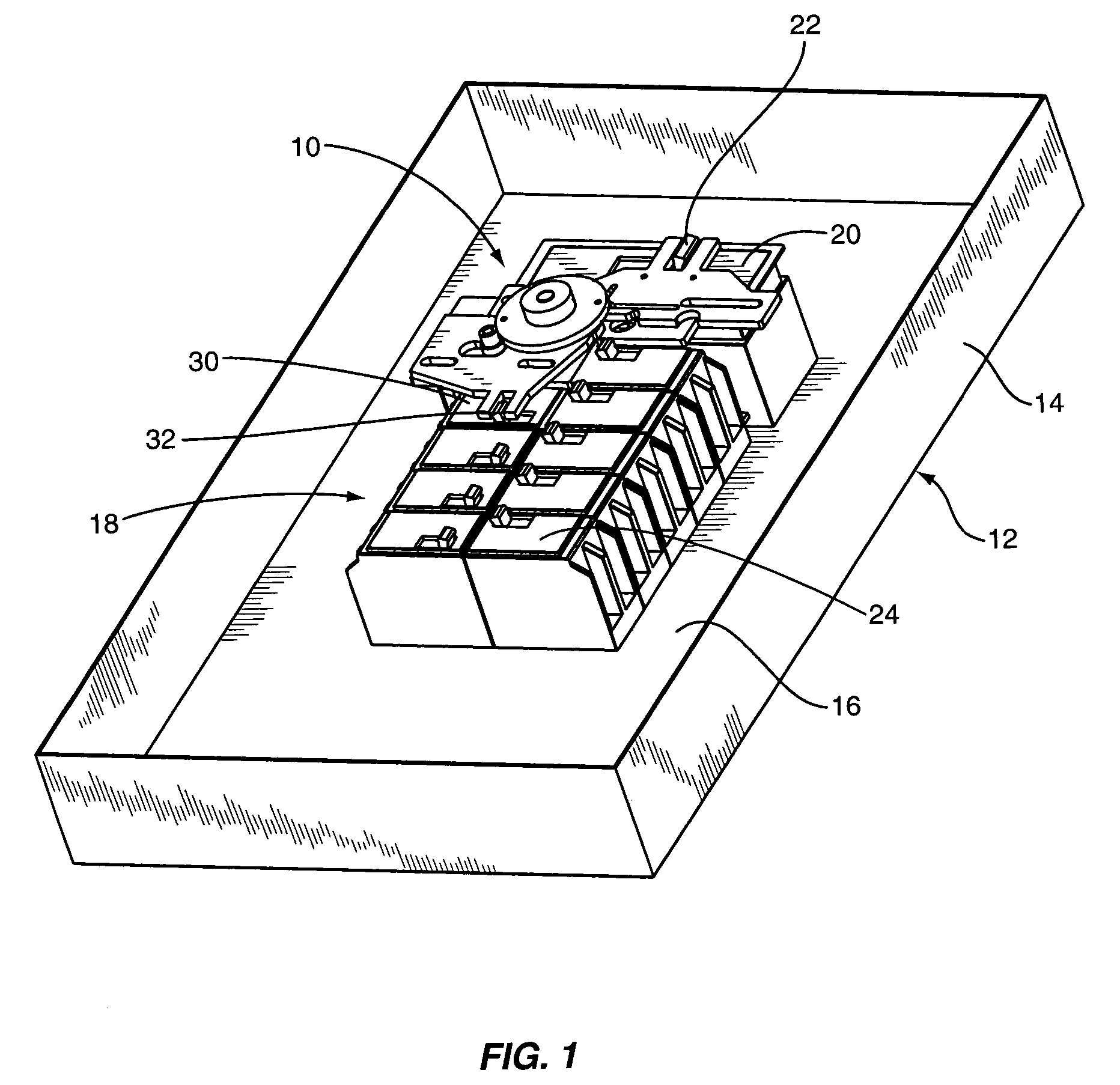
[0025]FIGS. 1–3 illustrate a switching mechanism indicated generally at 10 installed in an electrical distribution panel 12. The distribution panel 12 comprises a cabinet 14, a back plane 16 with interior parts (not shown), and a plurality of circuit breakers 18 including a main circuit breaker 20, a backup circuit breaker 30 and a number of branch circuit breakers 24. The main circuit breaker 20 connects the electrical distribution panel 12 to commercial power supply lines. The backup circuit breaker 30 connects the electrical distribution panel 12 to a local generator. The branch circuit breakers 24 connect the various loads in the residence or building to the electrical distribution panel 12. The switching mechanism 10 in combination with the main circuit breaker 20 and backup circuit breaker 22 function as a transfer switch.

[0026]The switching mechanism 10 comprises three main assemblies—a support assembly 100, an actuator assembly 200, and a drive assembly 300. The support asse...


PUM


Abstract

A switching mechanism provides sequential switching of first and second circuit breakers to enable switching between a primary power supply and a backup power supply. The switching mechanism comprises an actuating mechanism to sequentially actuate a pair of circuit breakers. The actuator mechanism including a shock absorber to absorb energy due to switching of one of the first and second circuit breakers.

Description

BACKGROUND OF THE INVENTION[0001]The present invention relates to transfer switches for switching between alternate power sources, such as commercial power supply lines and a local generator.[0002]Many residents now have a stand-by power supply such as a gas-powered generator for use in homes and other buildings during power outages. Power from the local generator can be supplied to a main distribution panel or sub-panel through a transfer switch when a power outage occurs. The transfer switch disconnects the home or building from the commercial power supply lines and connects the home or building to the local generator.[0003]The installation of a transfer switch typically requires the replacement of the main distribution panel in the home or building with a larger distribution panel to accommodate the transfer switch, or the installation of a separate sub-panel containing the transfer switch and additional circuit breakers. The cost of parts and labor to install a transfer switch c...

Claims


Application Information

Patent Timeline
Patent Type & Authority Patents(United States)
IPC IPC(8): H01H1/20H01H9/20H01H9/26
CPCH01H3/26H01H3/60H01H2300/018
Inventor FILLPPENKO, ALEXANDER S.POLLARD, GARY
Owner SQUARE D CO
Why Eureka
Try Eureka