
Capillary electrophoresis devices

a capillary electrophoresis and electrophoresis technology, applied in the direction of electrolysis components, laboratory apparatus, material analysis by electric/magnetic means, etc., can solve the problems of reducing the efficiency of the overall separation, microfabrication still suffers some drawbacks, and high fabrication costs, so as to reduce the cost of manufacturing the microfabrication device, the effect of reducing the size of the device and reducing the cost of the manufacturing of the devi

Active Publication Date: 2007-05-01
AST MANAGEMENT
View PDF57 Cites 22 Cited by
  • Summary
  • Abstract
  • Description
  • Claims
  • Application Information

AI Technical Summary

Benefits of technology

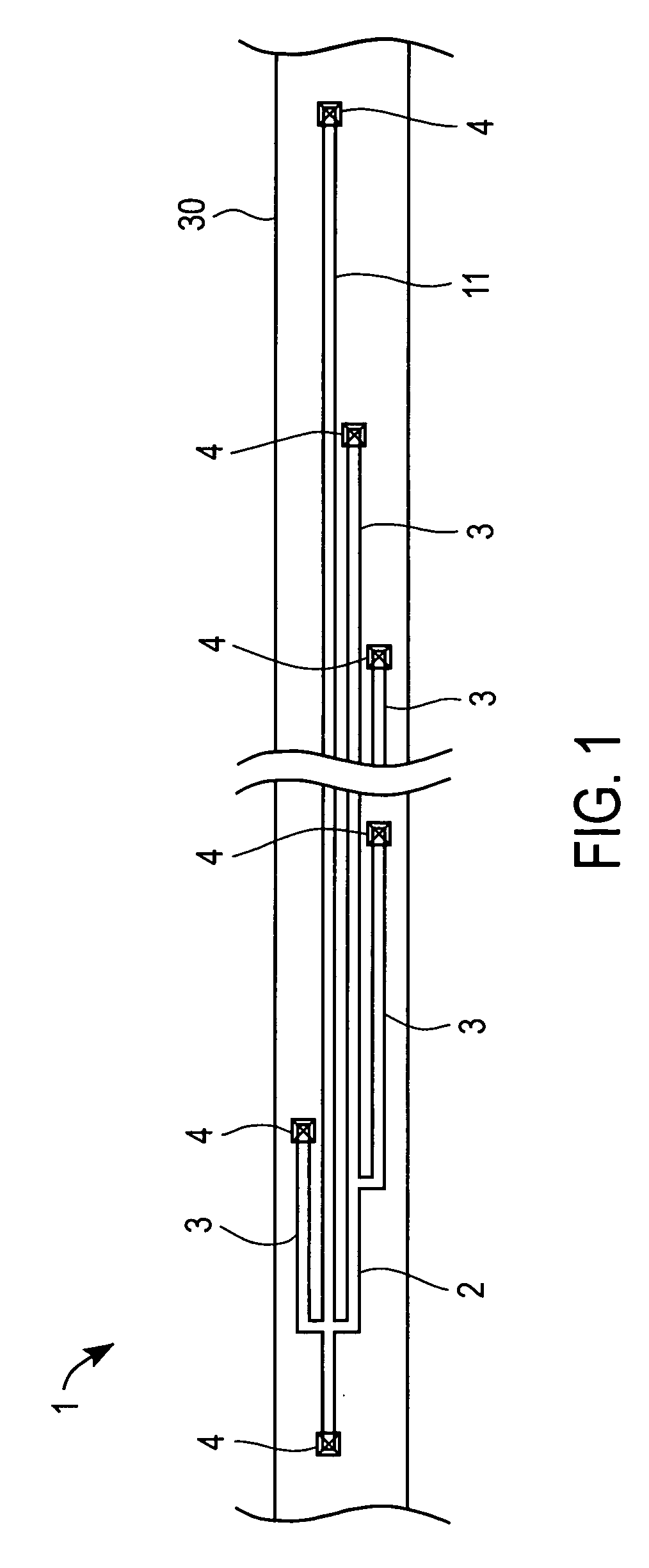
[0007]The present invention provides capillary electrophoresis devices featuring long straight channels as well as microfabrication methods for making such device that minimize device size. Another aspect of the present invention is the provision of capillary electrophoresis devices featuring long and straight channels that allow for the addition of liquid access to such channels. Still another aspect of the present invention is the provision of methods for preparing a capillary electrophoresis chip as well as a capillary electrophoresis device that employs long and straight channels, in which the device size is considerably reduced therefore lowering the cost of manufacturing the microfabrication device.
[0008]Still another aspect of the present invention is the provision of a capillary electrophoresis chip that is constructed from glass and silicon using microfabrication techniques. Another aspect of the present invention provides a capillary electrophoresis device that uses an injection molding plastic structure to package the capillary electrophoresis chip and to support sample loading, therefore lowering the manufacturing costs.

Problems solved by technology

However, these microfabrications still suffer some drawbacks.
First, microfabrication with long channel length requires large size devices, resulting in expensive fabrication costs.
Unfortunately, such curved channels inevitably reduce the efficiency of the overall separation compared with that of a straight separation channel.
The drilling process that drills holes through the substrate layers to access the microchannels also increases the device size.

Method used


Image

  • Capillary electrophoresis devices
  • Capillary electrophoresis devices
  • Capillary electrophoresis devices

Examples


example 1

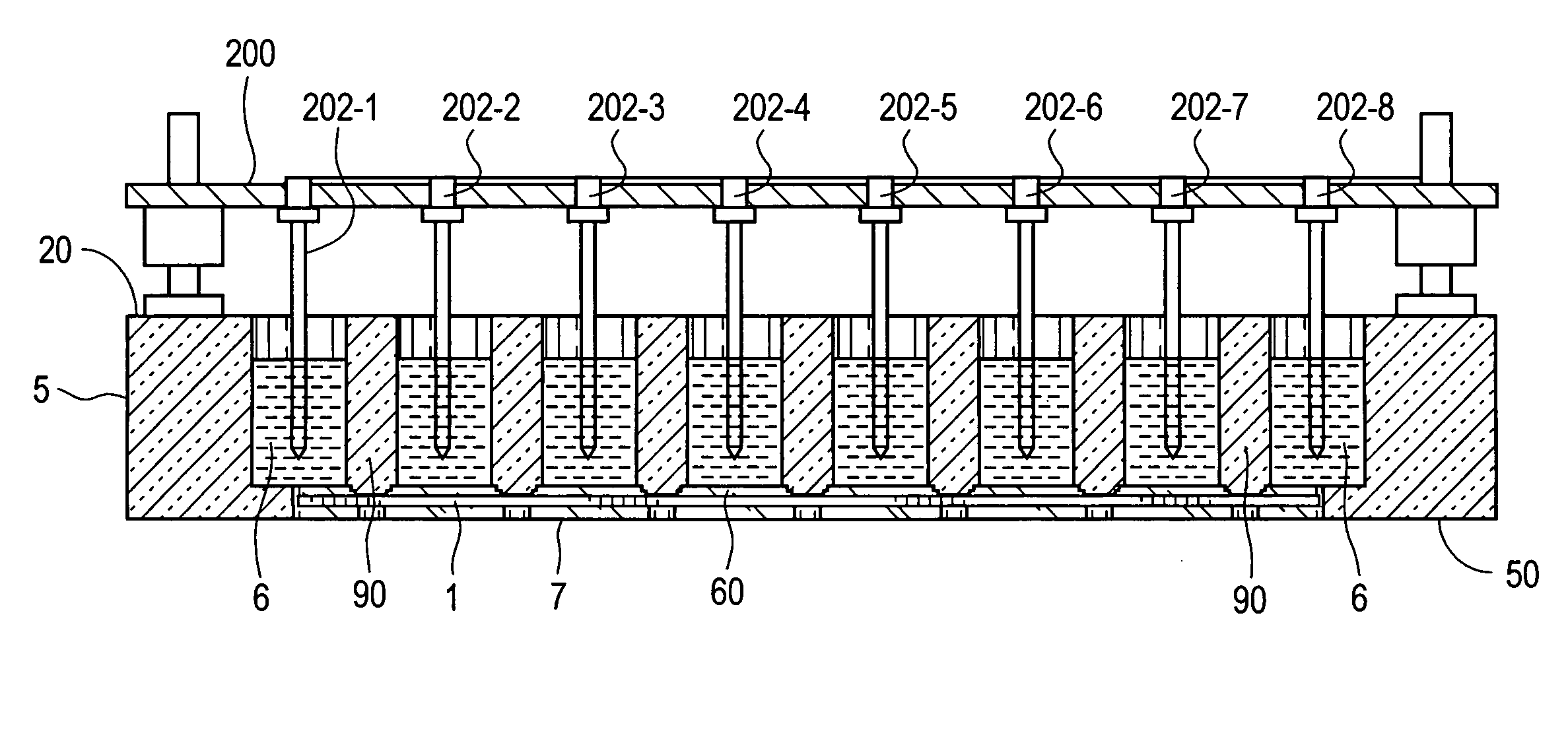
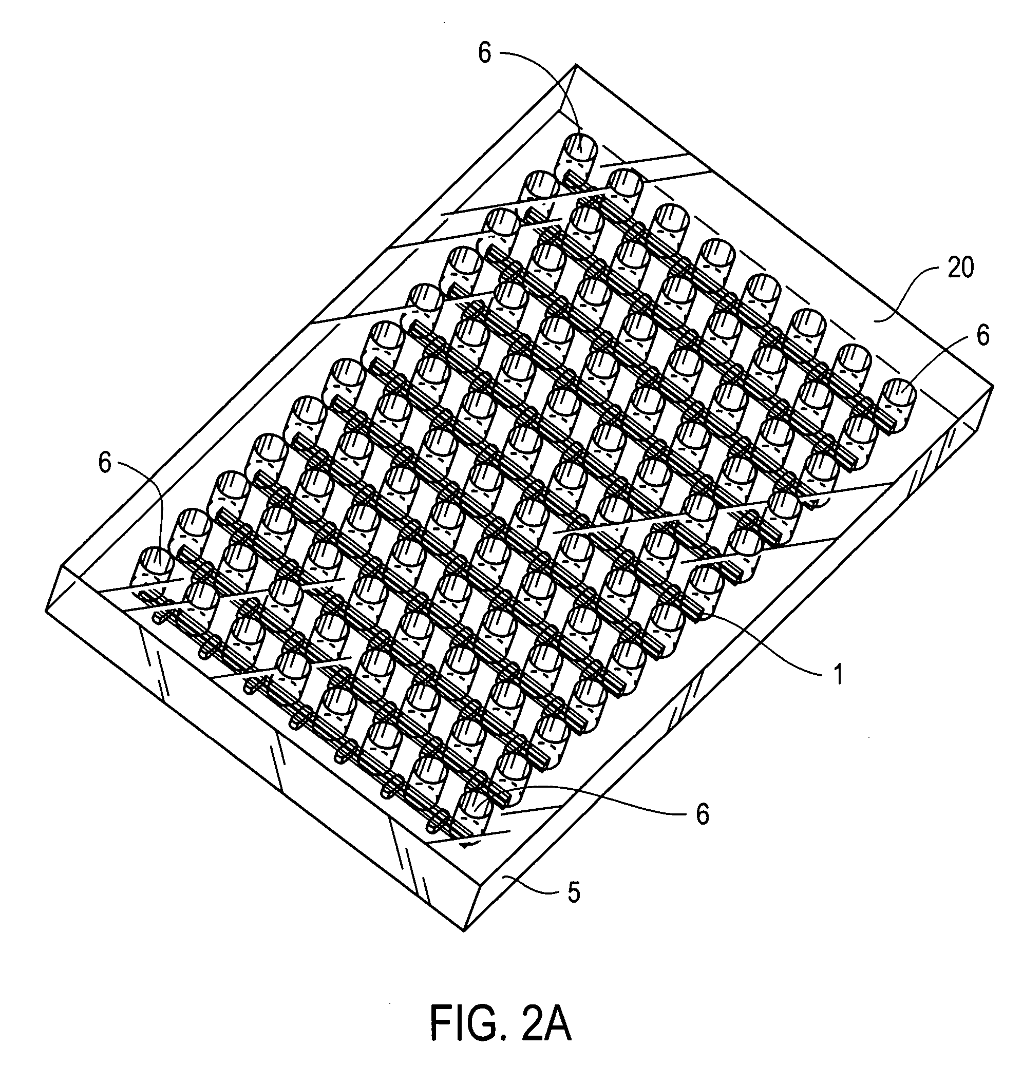
[0086]Device description. As illustrated in FIG. 18, a 1-sample CE chip is packaged into a package device 5. There are four inlet / outlets in CE chip 1. In FIG. 18, these inlet / outlets are located in reservoirs 1,2,3, and 8.

[0087]Buffer loading. About 30 μl of buffer is loaded into reservoir 8 of FIG. 18. Next, a syringe is used to force all of the channels in the CE chip 1 to become filled with buffer. Then, about 30 μl of buffer is loaded to reservoirs 1 and 3 of FIG. 18.

[0088]Sample loading and prerun. About 10 μl–20 μl of a liquid DNA sample (ΦX174 labeled by the fluorescence dye) is loaded into reservoir 2 of FIG. 18. An electrode 202 is placed in each reservoir. See, for example, FIG. 13. Then, the electrode potential configuration illustrated in FIG. 20 is used to prerun the separation channel.

[0089]Sample injection. The voltage setting is changed to injection mode. In injection mode, the electrode potential configuration is that of FIG. 19. Because of the difference in the el...


PUM

PropertyMeasurementUnit
diameteraaaaaaaaaa
diameteraaaaaaaaaa
widthaaaaaaaaaa

Abstract

A capillary electrophoresis device as well as a process for fabrication of the device is disclosed. The capillary electrophoresis device comprises a device body structure having a plurality of reservoirs arrayed thereon for loading a sample, and a plurality of rows of grooves transversely defined to be connected with the reservoirs for receiving at least a capillary electrophoresis chip. The capillary electrophoresis chip comprises a straight main separation channel, an injection channel, and a plurality of sample transport channels defined thereon in liquid communication with the reservoirs. After an electrode means is applied, the sample can be transported into the separation channel for detection and analysis.

Description

FIELD OF INVENTION[0001]The present invention relates to a capillary electrophoresis device, more particularly, relates to a capillary electrophoresis device implementing a microfabricated capillary electrophoresis chip being packaged into an injection-molding plastic structure for sample loading and electrophoresis function, as well as a method for preparing the microfabricated capillary electrophoresis chip and the capillary electrophoresis device.BACKGROUND[0002]Capillary electrophoresis is a technique for moving samples of interest through a solution filled capillary by means of an electric field. In such a way, molecules of different mobilities are separated into distinct zones for detection. In the 1990's, significant research effort in the field of capillary electrophoresis was focused on implementation of such capillary electrophoresis devices in microfabricated formats. Such formats provided significant advantages in terms of precision. As a result, micromachining and minia...

Claims


Application Information

Patent Timeline
Patent Type & Authority Patents(United States)
IPC IPC(8): G01N27/453
CPCB01L3/5025B01L3/502707B01L3/502715G01N27/44756B01L3/502753B01L2200/027B01L2300/0829B01L2400/0421
Inventor WEBSTER, JAMES RUSSELLKUO, YUAN-FONGWANG, SHAO-TSULEE, CHUN-HSIEN
Owner AST MANAGEMENT
Learn More