Liquid crystal display device and manufacturing method for the same
a technology of liquid crystal display and manufacturing method, which is applied in the direction of static indicating devices, non-linear optics, instruments, etc., can solve the problems of reducing the contrast of an image, reducing the visibility of an image, and complicated process for forming ruggedness on the surface of the reflection electrode, etc., to achieve good display quality, high luminance display, and color purity of the reflection mode display closer
- Summary
- Abstract
- Description
- Claims
- Application Information
AI Technical Summary
Benefits of technology
Problems solved by technology
Method used
Image
Examples
first embodiment
(First Embodiment)
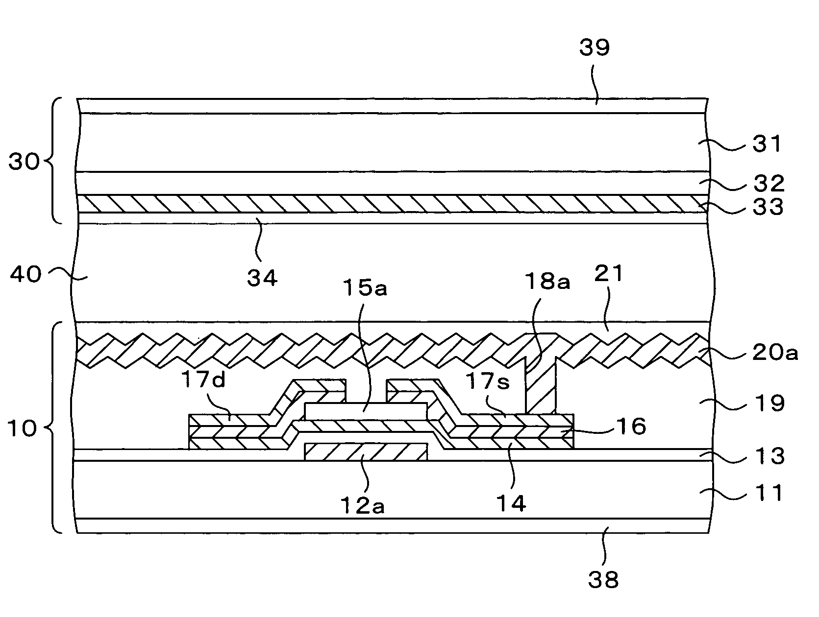
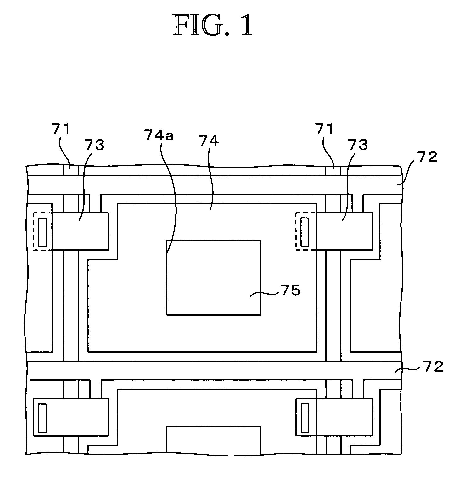
[0079]FIG. 7 is a plan view showing a liquid crystal display device of a first embodiment of the present invention, and FIG. 8 is a schematic sectional view taken along the line III—III of FIG. 7. Note that this embodiment shows an example in which the present invention is applied to a transflective type liquid crystal display device using a VA (vertically aligned) type liquid crystal.
[0080]As shown in FIG. 8, the liquid crystal display device of this embodiment is constituted including a TFT substrate 10 and a counter substrate 30, and a vertically aligned nematic liquid crystal 40. The TFT substrate 10 and the counter substrate 30 face each other, and the vertically aligned nematic liquid crystal 40 is enclosed between these substrates. Polarizing plates (linear polarizing plate or circular polarizing plate having the linear polarized light +λ / 4 phase difference combined) 38 and 39 are arranged under the TFT substrate 10 and on the counter substrate 30, respectiv...
second embodiment
(Second Embodiment)
[0114]FIG. 13A is a plan view showing a transflective type liquid crystal display device of a second embodiment of the present invention. This embodiment is different from the first embodiment in that the reflection electrode is provided with slits. The other structure is basically the same as that of the first embodiment, and therefore overlapping explanation will be omitted.
[0115]In this embodiment, as shown in FIG. 13A, a plurality of slits 52 are provided on a reflection electrode 51 and a resist film disposed thereunder, in parallel to the gate bus line 12a. That is, by these slits 52, the resist film is divided into a plurality of regions in one picture element.
[0116]As described before, a rugged pattern formed on the resist film is determined depending on the size of the resist film. Like this embodiment, by providing the slits 52 on the reflection electrode 51 and the resist film thereunder, a desired rugged pattern can be formed on the reflection electrod...
third embodiment
(Third Embodiment)
[0120]FIG. 16A is a plan view showing a transflective type liquid crystal display device of a third embodiment of the present invention. Note that this embodiment is different from the first embodiment in that the reflection electrode is not provided with a rugged surface, and the reflection electrode is provided with slits. The other structure is basically the same as that of the first embodiment, and therefore overlapping explanation will be omitted.
[0121]In this embodiment, as shown in FIG. 16A, a reflection electrode 61 is provided with slits 62, and slit 62 portions serve as transmission regions. Slits 63 and 64 in the shapes as shown in FIGS. 16B and 16C, respectively, may also be provided. However, the shapes of the slits are preferably common to each picture element. Moreover, any short side of the regions divided by the slits is preferably 5 m or more.
[0122]In this embodiment, the reflection electrode 61 is formed so as to overlap the gate bus line 12a, th...
PUM
| Property | Measurement | Unit |
|---|---|---|
| thickness | aaaaa | aaaaa |
| length | aaaaa | aaaaa |
| voltages | aaaaa | aaaaa |
Abstract
Description
Claims
Application Information
 - R&D
- Intellectual Property
- Life Sciences
- Materials
- Tech Scout
- Unparalleled Data Quality
- Higher Quality Content
- 60% Fewer Hallucinations
Browse by: Latest US Patents, China's latest patents, Technical Efficacy Thesaurus, Application Domain, Technology Topic, Popular Technical Reports.
© 2025 PatSnap. All rights reserved.Legal|Privacy policy|Modern Slavery Act Transparency Statement|Sitemap|About US| Contact US: help@patsnap.com


