
Inkjet head and method of cleaning inkjet head

a technology which is applied in the field of inkjet head and inkjet nozzle cleaning method, can solve the problems of affecting the cleaning effect of the inkjet head, affecting the quality of printing, so as to achieve the effect of efficient removal of fouling

Inactive Publication Date: 2007-04-24
FUJIFILM CORP
View PDF8 Cites 11 Cited by
  • Summary
  • Abstract
  • Description
  • Claims
  • Application Information

AI Technical Summary

Benefits of technology

The present invention provides an inkjet head and a method for cleaning it that can efficiently remove fouling around the nozzle without causing damage to the nozzle surface. The invention achieves this by using a boundary surface to collect the fouling and a device to move the boundary surface to different positions for recording and cleaning. The invention also includes a preliminary ink discharging mechanism to prevent impurities or ink droplets with increased viscosity from dispersing inside the pressure chamber of the inkjet head. The invention provides a more efficient and faster way to clean the inkjet head.

Problems solved by technology

If the vicinity of the nozzles becomes soiled to the ink mist, the paper dust, or the other dirt, the flight direction of the ink droplets discharged from the nozzles might change and the achievement of high quality printing might be impossible.
However, in this method, since the blade slides on and wipes off the nozzle surface, a drawback arises in that it may cause scratches in the nozzle surface or deterioration of the surface processing such as liquid resistance treatment, and stable discharge of the ink over a long period of time might become impossible.
However, the method disclosed in Japanese Patent Application Publication No. 3-293140 implies a problem in that, since an incomplete pulse or drive waveform resulting in incomplete discharge is supplied in order to create the column-shaped ink for collecting the fouling which is not discharged, the state of the ink droplets is extremely unstable.
In some cases, it might be impossible to collect the ink droplets depending on ambient temperature, etc.
This relates to collection of fouling in the case that the ink adheres to the nozzle surface due to capping, but is not applicable to a case that the fouling is separated from the ink meniscus inside the nozzle.

Method used


Image

  • Inkjet head and method of cleaning inkjet head
  • Inkjet head and method of cleaning inkjet head
  • Inkjet head and method of cleaning inkjet head

Examples


Embodiment Construction

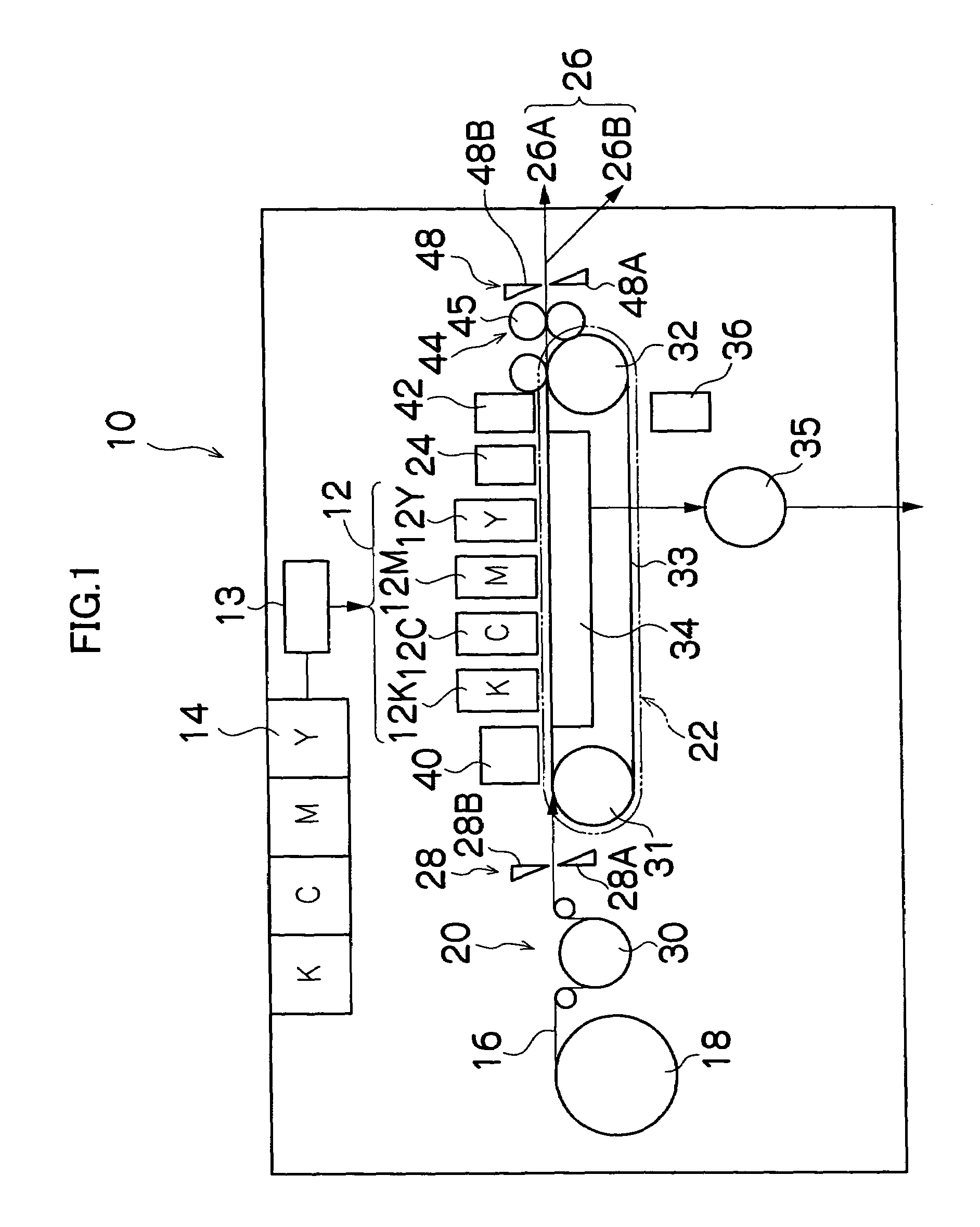
[0041]FIG. 1 is a general schematic drawing of an inkjet recording apparatus according to an embodiment of the present invention. As shown in FIG. 1, the inkjet recording apparatus 10 comprises: a printing unit 12 having a plurality of print heads 12K, 12C, 12M, and 12Y for ink colors of black (K), cyan (C), magenta (M), and yellow (Y), respectively; an ink storing / loading unit 14 for storing inks to be supplied to the print heads 12K, 12C, 12M, and 12Y; a paper supply unit 18 for supplying recording paper 16; a decurling unit 20 for removing curl in the recording paper 16; a suction belt conveyance unit 22 disposed facing the nozzle face (ink-roplet ejection face) of the print unit 12, for conveying the recording paper 16 while keeping the recording paper 16 flat; a print determination unit 24 for reading the printed result produced by the printing unit 12; and a paper output unit 26 for outputting image-printed recording paper (printed matter) to the exterior.

[0042]In FIG. 1, a si...


PUM


Abstract

The inkjet head comprises: a nozzle which discharges droplets of ink through an ink discharge port to perform recording onto a recording medium, the ink being supplied through a supply duct, at least partial cross section of the nozzle on a side of the ink discharge port broadening toward the ink discharge port; and a device which moves a position of a boundary surface of the ink between a first boundary surface keeping position inside the nozzle at which the boundary surface of the ink is kept for recording and a second boundary surface keeping position inside the nozzle at which the boundary surface of the ink is kept for cleaning the nozzle under pressure less than or equal to ink discharging pressure, wherein fouling around the nozzle is collected by moving the position of the boundary surface of the ink between the first boundary surface keeping position and the second boundary surface keeping position.

Description

[0001]This Non-provisional application claims priority under 35 U.S.C. § 119(a) on Patent Application No(s). 2003-321667 filed in Japan on Sep. 12, 2003, the entire contents of which are hereby incorporated by reference.BACKGROUND OF THE INVENTION[0002]1. Field of the Invention[0003]The present invention relates to an inkjet head and a method of cleaning the inkjet head, and more particularly to cleaning the inkjet head used in the inkjet recording apparatus so that fouling such as ink adhering around the inkjet head can be removed in a non-contact way without using a blade.[0004]2. Description of the Related Art[0005]An inkjet printer is known such that recording is performed by supplying ink to an inkjet head and discharging the ink in the form of ink droplets from nozzles of the inkjet head toward recording paper. Since an inkjet printer carries out recording by expelling (or discharging) ink from nozzles, a portion of the expelled ink is dispersed in the form of a fine mist. Thi...

Claims


Application Information

Patent Timeline
Patent Type & Authority Patents(United States)
IPC IPC(8): B41J2/165B41J2/14
CPCB41J2/16535B41J2/14233B41J2002/14475B41J2/1606B41J2/175
Inventor KOJIMA, TOSHIYAKODAMA, KENICHI
Owner FUJIFILM CORP
Learn More