
Electromagnetic piezoelectric acoustic sensor

a piezoelectric and acoustic sensor technology, applied in the field of acoustic wave sensors, can solve problems such as time-consuming and laborious

Inactive Publication Date: 2007-04-24
SENSORCHEM INT
View PDF4 Cites 17 Cited by
  • Summary
  • Abstract
  • Description
  • Claims
  • Application Information

AI Technical Summary

Benefits of technology

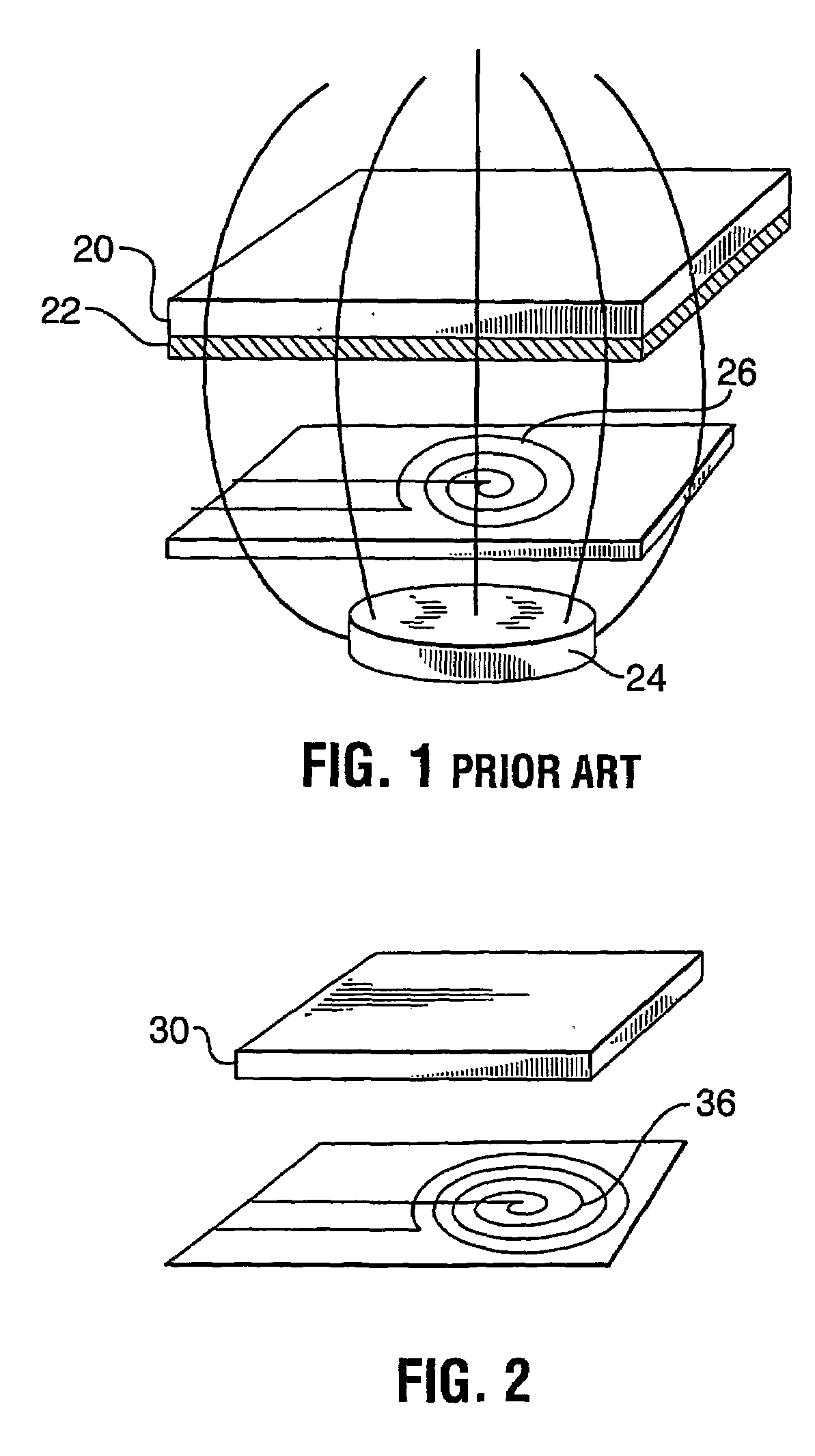
[0020]It is an object of the present invention to obviate or mitigate at least one disadvantage of previous acoustic wave sensors.

Problems solved by technology

However, this particle motion will be damped by the quartz's viscosity, and will therefore decay with time.

Method used


Image

  • Electromagnetic piezoelectric acoustic sensor
  • Electromagnetic piezoelectric acoustic sensor
  • Electromagnetic piezoelectric acoustic sensor

Examples


example 1

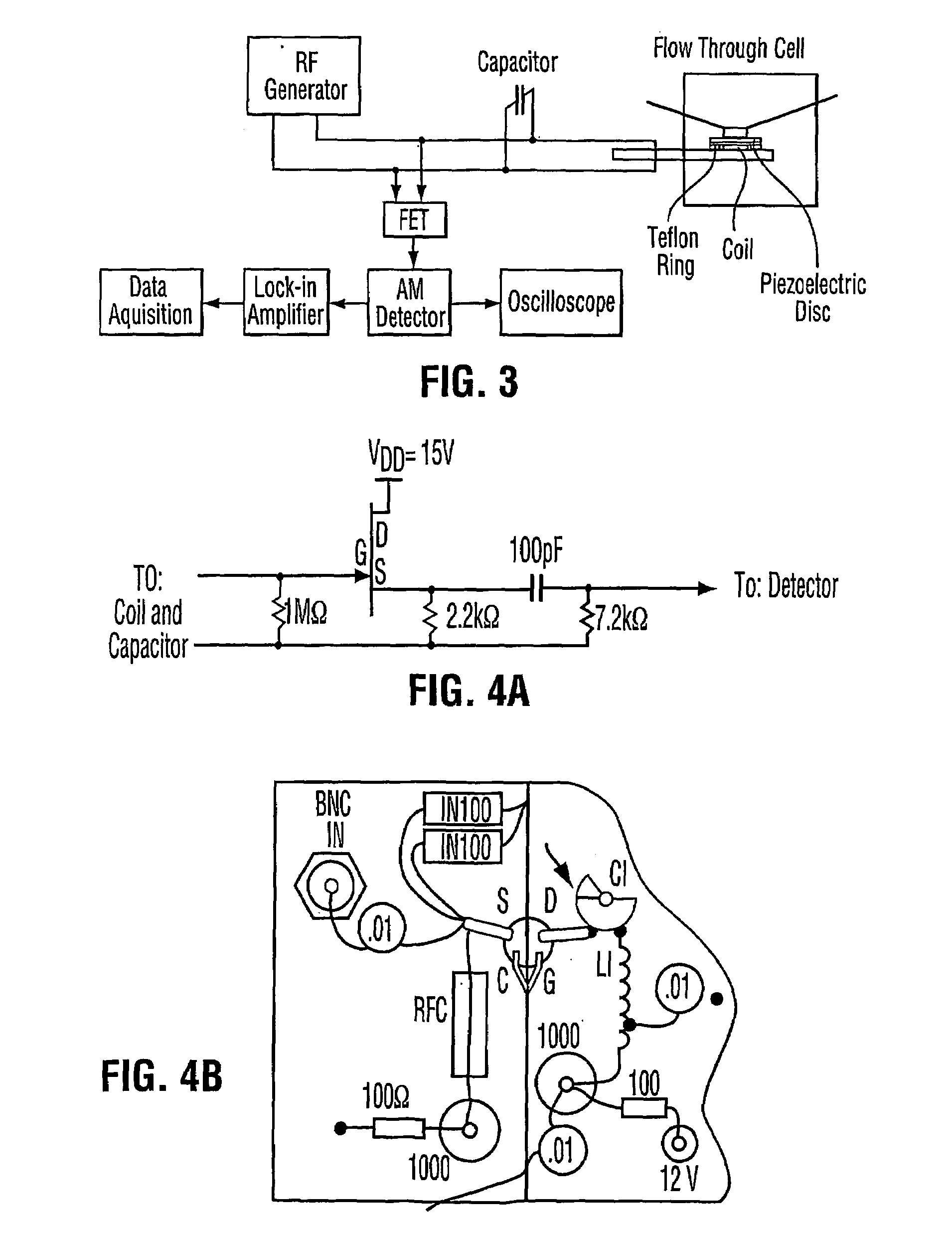
[0086]Methodology. Resonance envelopes were generated in air and liquid by soft clamping a crystal (an AT cut quartz disc having a gold electrode thereon) in a flow through cell (internal volume approx. 70 μL). Resonance envelopes generated in liquid were acquired in Tris buffer (7.5 pH); prepared by adding 5 mL of 1 mol / L Tris+7 mL 5 mol / L NaCl+0.2 mL of 0.5 mol / L EDTA+487.8 mL distilled water. Flow rates were maintained at approximately 0.6 mL / min. In this example, the field effect transistor is of the type shown in FIG. 4A.

[0087]Protein injection experiments involved the use of neutravidin (non-glycosylated version of avidin). The neutravidin was dissolved in the tris buffer to make a 1 mg / mL solution. Buffer was flown through the cell for 10 minutes, then 500 μL of the neutravidin solution was injected, followed by flowing buffer. All experiments were conducted using 45 MHz carrier signal. Data was processed and displayed via NI Labview™ program software.

[0088]Results. FIG. 7 sh...

example 2

[0098]Methodology. Resonance envelopes were generated in air and liquid by soft clamping a crystal (an AT-cut quartz disc “blank”, having no metal electrode thereon) in the flow through cell (internal volume approx. 70 μL). Resonance envelopes generated in liquid were acquired in Tris buffer (7.5 pH); prepared by adding 5 mL of lmol / L Tris+7 mL 5 mol / L NaCl+0.2 mL of 0.5 mol / L EDTA+487.8 mL distilled water. Flow rates were maintained at approximately 0.6 mL / min. In this example, the field effect transistor is of the type shown in the schematic of FIG. 4B.

[0099]Protein injection experiments involved the use of neutravidin (non-glycosylated version of avidin). The neutravidin was dissolved in the tris buffer to make a 1 mg / mL solution. Buffer was flown through the cell for 10 minutes, then 500 μL of the neutravidin solution was injected, followed by flowing buffer. All experiments were conducted using 45 MHz carrier signal. Data was processed and displayed via NI Labview™ program soft...


PUM

PropertyMeasurementUnit
thickaaaaaaaaaa
frequencyaaaaaaaaaa
frequencyaaaaaaaaaa

Abstract

The invention relates to an electromagnetic piezoelectric acoustic sensor (EMPAS). The sensor comprises a piezoelectric sensor plate spaced apart from an induced dynamic electromagnetic field, such as from an electromagnetic coil through which AC current flows. The electromagnetic field induces vibration in the sensor plate by fluctuating the aligned dipole moments of the piezoelectric material. Changes on the surface of the sensor plate can be detected by variation in resonance frequency of the sensor plate. The invention represents an improvement over conventional sensor methodologies in that no metallization of the sensor surface is required, and no permanent magnet is needed. The sensor may be used to detect absorption of molecules or biomolecular interactions between probe and target molecules.

Description

[0001]This application claims priority from Canadian Patent Application No. 2,356,044 filed Aug. 28, 2001, and from U.S. Provisional Patent Application 60 / 375,436 filed Apr. 26, 2002. The content of both documents is incorporated by reference herein.FIELD OF THE INVENTION[0002]The present invention relates generally to an acoustic wave sensor, and particularly to an acoustic sensor incorporating piezoelectric material.BACKGROUND OF THE INVENTION[0003]Acoustic wave transducers are conventionally divided into bulk acoustic wave (BAW) and surface acoustic wave (SAW) devices. The majority of BAW devices employ a 0.2 to 0.5 mm thick AT-cut quartz resonator disc coated with metal electrodes, such as gold electrodes, on either side of the disc. A high frequency (low MHz) sinusoidal voltage is applied across the gold electrodes causing the quartz resonator disc to oscillate at its resonant frequency. When used as a mass sensor, this device is referred to as a quartz crystal microbalance (QC...

Claims


Application Information

Patent Timeline
Patent Type & Authority Patents(United States)
IPC IPC(8): G01N29/00G01N29/04G08B3/02G01N27/00G01N33/543H04R17/00
CPCG01N29/036G01N33/54373G01N2291/0256G01N2291/0257
Inventor THOMPSON, MICHAELBALLANTYNE, SCOTT
Owner SENSORCHEM INT
Learn More